Crimp terminal, connection structural body, connector, wire harness, method of manufacturing crimp terminal, and method of manufacturing connection structural body

a technology of connecting structural body and crimp terminal, which is applied in the direction of connecting contact member material, dustproof/splashproof/drip-proof/waterproof/flameproof connection, etc., can solve the problems of increasing the time and cost required for processing, the cylindrical section of the connection piece and the wire may not be able to be formed in the desired shape, and the desired function of the connection piece and the wire is not fully satisfied. , to achieve the effect of excellent degree of design

Active Publication Date: 2015-03-05
FURUKAWA ELECTRIC CO LTD +1
View PDF16 Cites 27 Cited by
  • Summary
  • Abstract
  • Description
  • Claims
  • Application Information

AI Technical Summary

Benefits of technology

[0090]According to the present invention, a crimp terminal, a connection structural body, a connector, a wire harness, a method of manufacturing a crimp terminal, and a method of manufacturing a connection structural body each having an excellent degree of freedom for design that enables a pressure-bonding section and a terminal connection section to be appropriately configured depending on functions required therefor can be provided.

Problems solved by technology

However, when the entire wire connection terminal is integrally manufactured by one member, in spite of that fact that a connection piece connected to a device and a wire insertion cylindrical section connected to the core wire of the wire are required to have different functions such as water-blocking performance and strength and different levels thereof, the connection piece and the wire insertion cylindrical section are restricted to be made of the same material and to have the same thickness, for example.
Desired functions required for the connection piece and the wire insertion cylindrical section are not completely satisfied.
For this purpose, an advanced processing technique is required, and time and cost required for the processing increase.
The connection piece and the wire insertion cylindrical section may not be able to be formed in desired shapes.
In order to increase the strength of the boundary portion between the parts, an entire thickness need to be increased, and a material cost disadvantageously increases.
In this manner, when the crimp terminal is integrally manufactured, a degree of freedom for design is restricted, and a problem in which portion of the crimp terminal such as a wire connection section, a pressure-bonding section, and a boundary portion therebetween cannot be formed while securing the desired functions is posed.

Method used


Image

  • Crimp terminal, connection structural body, connector, wire harness, method of manufacturing crimp terminal, and method of manufacturing connection structural body
  • Crimp terminal, connection structural body, connector, wire harness, method of manufacturing crimp terminal, and method of manufacturing connection structural body
  • Crimp terminal, connection structural body, connector, wire harness, method of manufacturing crimp terminal, and method of manufacturing connection structural body

Examples


first embodiment

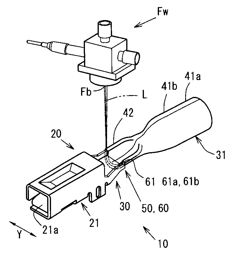
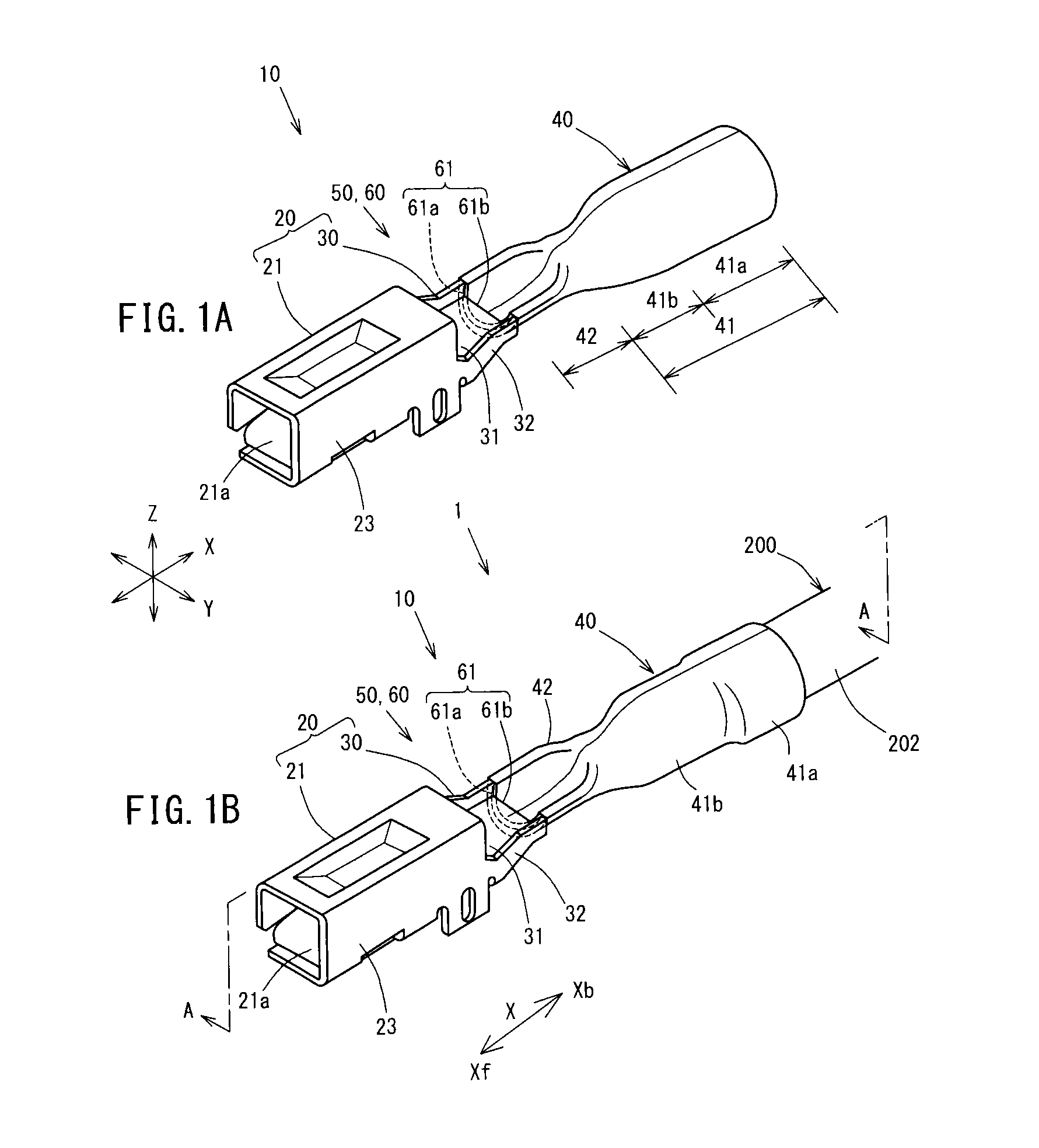
[0112]FIG. 1A is a perspective view of a female crimp terminal 10 according to a first embodiment, and FIG. 1B is a perspective view of a crimp terminal-bearing wire 1 according to the first embodiment.

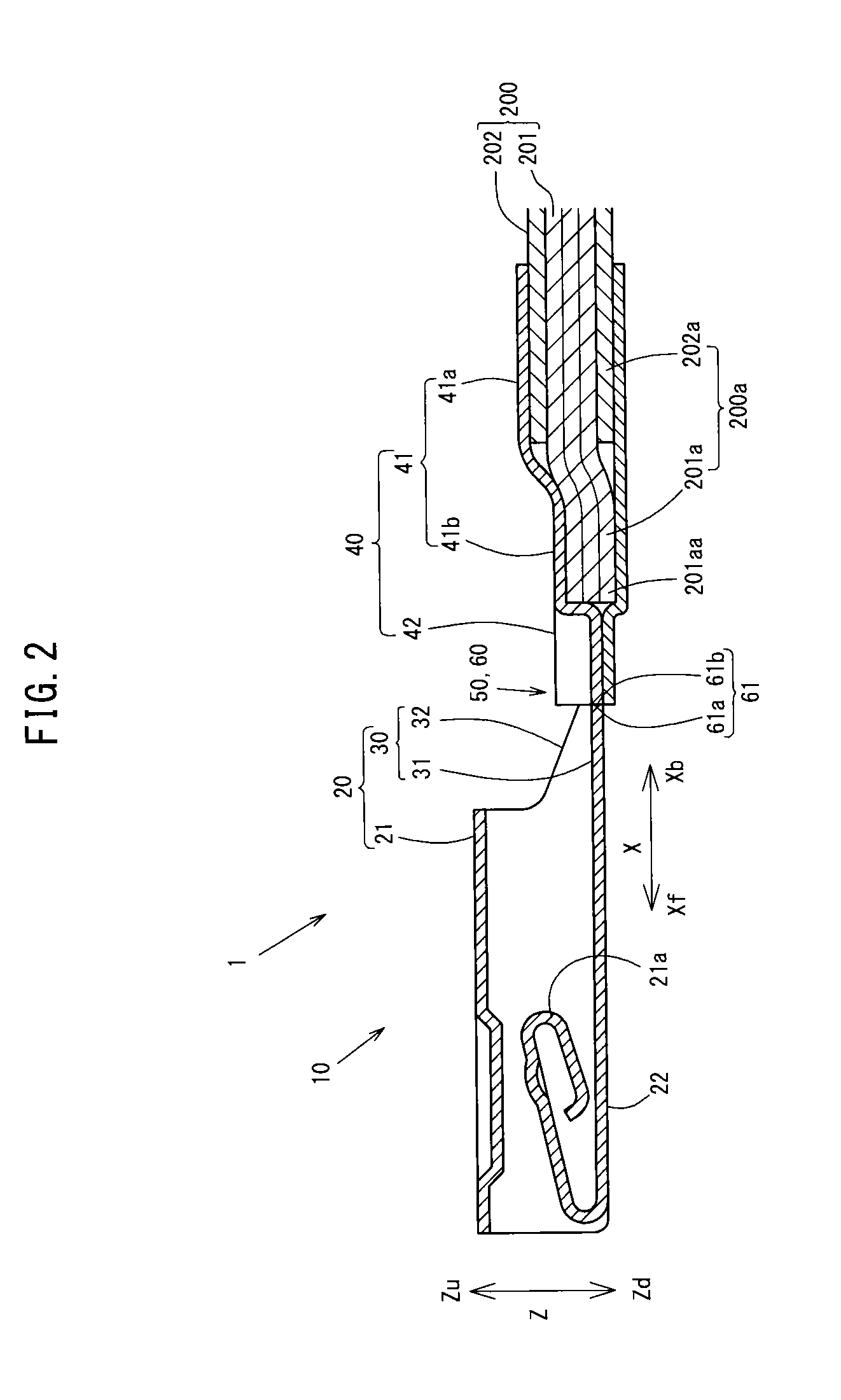
[0113]FIG. 2 is a longitudinal sectional view of an intermediate portion of the crimp terminal-bearing wire 1 according to the first embodiment in a width direction, and is a sectional view along A-A line in FIG. 1B.

[0114]The crimp terminal-bearing wire 1 according to the embodiment, as shown in FIG. 1B and FIG. 2, is configured by connecting an insulated wire 200 to the female crimp terminal 10. This will be described in more detail. A wire tip 200a of the insulated wire 200 is connected to a pressure-bonding section 40 of the female crimp terminal 10 by pressure bonding.

[0115]The insulated wire 200 pressure-bonded to the female crimp terminal 10 is configured such that an aluminum core wire 201 obtained by bundling aluminum raw wires 201aa is coated with an insulating cover 202 made...

second embodiment

[0185]FIGS. 6A and 6B are diagrams for explaining a female crimp terminal 10Pa and a crimp terminal-bearing wire 1Pa according to a second embodiment. This will be described in more detail. FIG. 6A shows a state in which a pressure-bonding section 40Pa and the terminal connection section 20 configured by different members are arranged to be opposed to each other. FIG. 6B is a longitudinal sectional view showing a part of the crimp terminal-bearing wire 1Pa according to the second embodiment.

[0186]The crimp terminal-bearing wire 1Pa according to the second embodiment include the female crimp terminal 10Pa configured by the pressure-bonding section 40Pa and the terminal connection section 20.

[0187]In the female crimp terminal 10Pa, as shown in FIG. 6A, a long length direction facing end 62 of the pressure-bonding section 40Pa does not have an end shape having a U-shape as described above. As in the terminal connection section 20, the long length direction facing end 62 has an approxim...

third embodiment

[0191]FIGS. 7A and 7B are diagrams for explaining a female crimp terminal 10Pb and a crimp terminal-bearing wire 1Pb according to a third embodiment, FIG. 7A shows a state in which the pressure-bonding section 40Pb and the terminal connection section 20Pb configured by different members are arranged to be opposed to each other. FIG. 7B is a longitudinal sectional view showing a part of the crimp terminal-bearing wire 1Pb according to the third embodiment.

[0192]The crimp terminal-bearing wire 1Pa according to the third embodiment, as shown in FIG. 7A, includes the female crimp terminal 10Pb configured by the pressure-bonding section 40Pb and the terminal connection section 20Pb.

[0193]In the female crimp terminal 10Pb according to the third embodiment, at the facing portions 60 where the pressure-bonding section 40Pb and the terminal connection section 20Pb face each other, long length direction facing surfaces 63 (63a and 63b) having a facing area larger than the facing area between ...


PUM

PropertyMeasurementUnit
outer diameteraaaaaaaaaa
widthaaaaaaaaaa

Abstract

A crimp terminal includes a pressure-bonding section to which at least a conductor tip of an insulated wire is connected by pressure bonding, the insulated wire in which a conductor is covered with an insulating cover and an insulating cover on a tip side is peeled to expose the conductor to obtain the conductor tip, and a terminal connection section to which another connection terminal is allowed to be connected. The terminal connection section and the pressure-bonding section are configured as different parts, and a connection section in which the terminal connection section and the pressure-bonding section are connected in series in the order named from a tip side to a rear side in a long length direction is configured.

Description

TECHNICAL FIELD[0001]The present invention relates to a crimp terminal and a connection structural body that are fitted on a connector or the like of, for example, an automobile wire harness, a connector, and a method of manufacturing a connection structural body.BACKGROUND ART[0002]An electric appliance fitted on an automobile or the like is connected to another electric appliance and a power supply device through a wire harness obtained by bundling insulated wires to configure an electric circuit. At this time, the wire harness and the electric appliance or the power supply device are connected such that connectors fitted thereon are connected to each other.[0003]Various crimp terminals arranged on the connectors are proposed, and a wire connection terminal disclosed in Patent Document 1 is one of the crimp terminals.[0004]On the wire connection terminal disclosed in Patent Document 1, a flat connection piece obtained by flattening out a front-half portion of a conductive metal pi...

Claims


Application Information

Patent Timeline
Patent Type & Authority Applications(United States)
IPC IPC(8): H01R4/18H01R43/02H01R9/11
CPCH01R4/183H01R43/0221H01R9/11H01R4/62H01R4/029H01R4/20H01R4/70H01R13/11H01R43/005Y10T29/49213
Inventor KAWAMURA, YUKIHIROTONOIKE, TAKASHIYAGI, SABURO
Owner FURUKAWA ELECTRIC CO LTD
Why Eureka
Try Eureka