Friction stir welding apparatus and method for joining workpieces by means of a friction stir welding process

Inactive Publication Date: 2015-03-12
TECH UNIV MUNCHEN
View PDF14 Cites 11 Cited by
  • Summary
  • Abstract
  • Description
  • Claims
  • Application Information

AI Technical Summary

Benefits of technology

The invention is a friction stir welding apparatus and process that solves the problems of the prior art. The apparatus has a simple structure and is easy to make and use. It produces high-quality work results. The design of the apparatus reduces the force on the machine tool spindle and allows for burrless joining without requiring re-working. The invention uses a sliding element instead of a stationary shoulder, which reduces the process forces and simplifies tool design and assembly. The clamping elements apply a contact force to the sliding element, reducing the force on the machine tool spindle and resulting in better work results. Overall, the invention improves friction stir welding and its use in various applications.

Problems solved by technology

However, the necessary anti-twist protection, in particular, which must be realized by an auxiliary element, often a bracket, has a negative impact.
With this auxiliary device, an automatic tool change, as is customary in modern metal-working machines, carries the risk of a collision.
A further drawback can be seen in the fact that the contact force of the stationary shoulder must be applied via the drives of the machine.

Method used


Image

  • Friction stir welding apparatus and method for joining workpieces by means of a friction stir welding process
  • Friction stir welding apparatus and method for joining workpieces by means of a friction stir welding process
  • Friction stir welding apparatus and method for joining workpieces by means of a friction stir welding process

Examples


Embodiment Construction

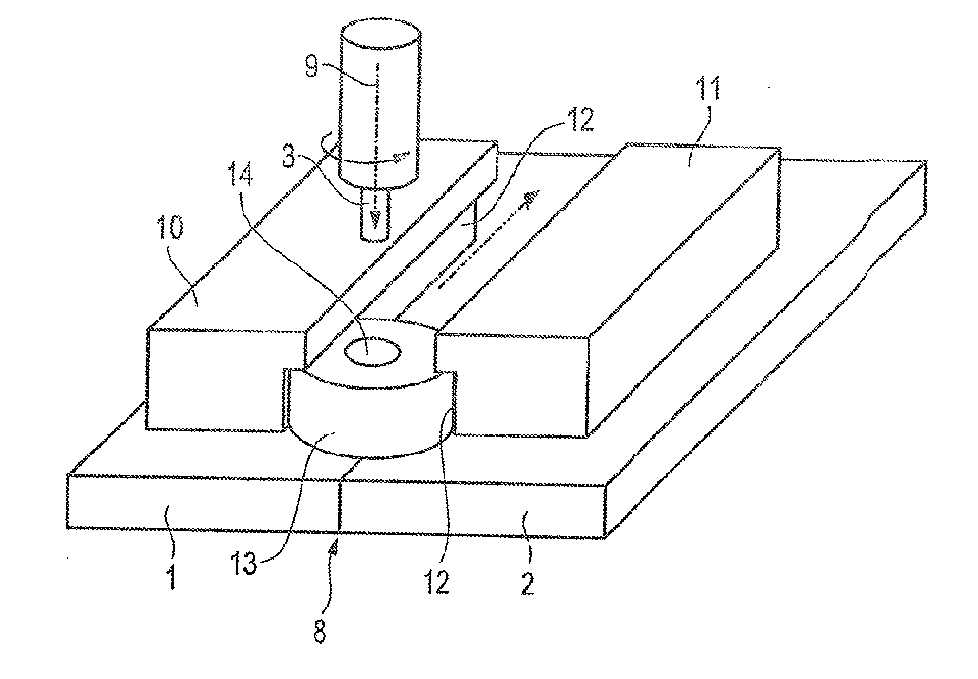
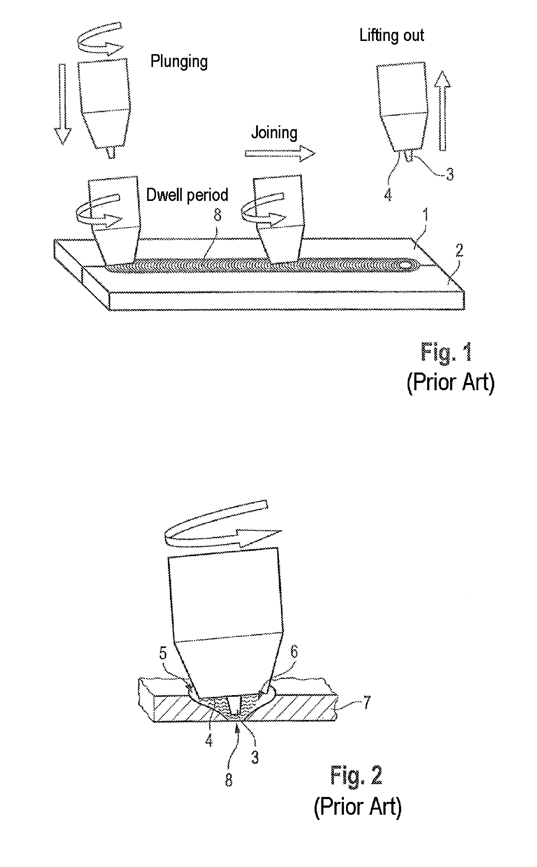
[0031]FIG. 1 shows in schematic representation the individual method steps of the friction stir welding according to the prior art. A friction stir welding tool has a welding pin 3 and is flattened off at its free end, so that an annular shoulder 4 is formed. The tool is firstly plunged into the joining region 8 of the workpieces 1, 2. The entire tool, inclusive of the welding pin 3, rotates hereupon. The tool dwells for a certain period in the joining zone 8 and is subsequently, as represented by the arrow, moved translatorily for the joining, wherein the tool is rotated about its center axis. As a result, both the welding pin 3 and the shoulder 4 enter into engagement with the plasticized material of the workpieces 1, 2.

[0032]FIG. 2 shows an enlarged detailed view of the joining region 8. A plasticization zone 6, produced by the rotation of the welding pin 3, is here represented. The reference symbol 5 shows the region warmed by the frictional heat, while the reference symbol 7 re...


PUM

PropertyMeasurementUnit
Forceaaaaaaaaaa

Abstract

The invention relates to a friction stir welding apparatus for joining workpieces 1, 2, having a welding pin 3, which is rotatable about its center axis 9 by means of a drive, and having at least one clamping apparatus for clamping the workpieces 1, 2 to be joined, characterized in that the clamping apparatus comprises at least two clamping elements 10, 11, which respectively have an undercut guideway 12, the guideways 12 being arranged parallel to one another and parallel to a joining region 8, in that between the clamping elements 10, 11 is arranged a sliding element 13, which is secured by the guideways 12 against the workpieces 1, 2 and is translatorily displaceable along the guideways 12, and in that the sliding element 12 is provided with an opening 14 for the lead-through of the welding pin 3, and further relates to a method for friction stir welding, using the above-stated apparatus.

Description

BACKGROUND OF THE INVENTION[0001]The invention relates to a friction stir welding apparatus for joining workpieces and to a method for joining workpieces by means of a friction stir welding process.[0002]The basic principles of friction stir welding processes are previously known, for example, from WO 93 / 10935 A1.[0003]FIG. 1 shows in schematic representation the flow of a friction stir welding process according to the prior art. Contrary to the conventional friction stir welding processes, the friction stir welding uses a wear-resistant tool, comprising a welding pin 3 and a shoulder 4, to produce an integrally bonded connection. The tool which is used is here contoured such that solid material can be sheared in the contact region and stirred together. The plasticization process is aided by the influence of the generated frictional heat. The process temperatures are typically in the realm of the recrystallization temperature of the base material, so that the parts to be joined are ...

Claims


Application Information

Patent Timeline
IPC IPC(8): B23K20/12
CPCB23K20/1245B23K20/126B23K20/1255
Inventor SUNGER, SAHINWIRTH, FRANZ XAVER
Owner TECH UNIV MUNCHEN
Why Eureka
Try Eureka