Friction stir welding appparatus

a friction stir and appparatus technology, applied in the direction of soldering apparatus, welding devices, manufacturing tools, etc., can solve the problems of the relative movement of the workpiece, the properties of the weld seam, and the robots do not have the required stability to absorb the force, so as to achieve the effect of improving the stir zone, and reducing the overall siz

Inactive Publication Date: 2006-12-28
GKSS FORSCHUNGSZENTRUM GEESTHACHT GMBH
View PDF36 Cites 57 Cited by
  • Summary
  • Abstract
  • Description
  • Claims
  • Application Information

AI Technical Summary

Benefits of technology

[0028] In a first alternative, the second friction surface segment can likewise be set in rotation by the first drive, resulting in an apparatus with the smallest possible overall size. In a second alternative, however, it is also possible to provide a second drive, which is used to drive the second friction surface segment. In this way, the second friction surface can be controlled independently of the first friction surface, so that the properties of the weld seam can be set even more successfully.
[0029] In another preferred embodiment, there is a passage with an outlet opening for introducing filler materials into the weld seam. Filler materials, in particular scandium powder, can be used to deliberately improve the properties of the stir zone in the region of the weld seam. Furthermore, the addition of the filler material allows special alloys to be formed in the region of the weld seam, which can improve the quality of the weld seam. For this purpose, the metal powder can be introduced into the weld seam through a passage in the pin and / or through an opening which may be formed in particular by the gap between the first friction surface segment and the first inner segment, which leads to particularly thorough mixing between the material of the workpieces and the filler material and therefore to a homogeneous weld seam.
[0030] In the case of the friction stir welding of workpieces made from aluminium or alloys thereof, the filler materials may in particular be copper, manganese, silicon, magnesium, zinc or aluminium oxide. In this context, copper has the advantage of increasing the tensile strength in the region of the weld seam. Manganese increases the strength without causing a loss of ductility. If silicon is introduced into the region of the weld seam, this reduces the melting temperature of the material which forms the weld seam. Magnesium as filler material is associated with the advantage of increasing the strength and corrosion resistance of the material of the weld seam compared to the aluminium of the workpieces that are to be joined. Zinc and magnesium also improve the tensile strengths. Aluminium oxide as filler material, finally, leads to an improvement in the surface hardness and wear resistance and to an increase in the strength.

Problems solved by technology

However, one drawback of friction welding is that a relative movement is required between the workpieces that are to be joined.
This constitutes a problem in particular if large workpieces are to be joined to one another, since this requires apparatuses and fixtures which have to hold the entire workpieces and move them with respect to one another.
However, the friction of the pin and the shoulder(s) exerts forces on the workpieces, and these forces have to be absorbed by a workpiece fixture.
If an apparatus for friction stir welding is to be used with a conventional robot, the problem often arises that on account of its design the robots do not have the required stability to absorb the forces generated by the pin and the shoulders and running in the plane of the weld seam.
A further problem is that the properties of the weld seam are determined by the temperature distribution and the mass transfer caused by the friction between pin and shoulder(s) and the workpieces.
Therefore, the properties of the weld seam can only be influenced by changing the rotational speed of the pin and shoulder(s) and the speed at which the pin is moved linearly along the joint, and consequently targeted influencing of the properties is only possible with difficulty.
Finally, the friction stir welding apparatuses which are known from the prior art are designed for a specific arrangement of the workpieces which are to be joined to one another and cannot be used for other geometries.
Therefore, when changing the type of workpiece, it is also necessary to change the friction stir welding apparatus, which involves changeover times and associated costs.

Method used


Image

  • Friction stir welding appparatus
  • Friction stir welding appparatus
  • Friction stir welding appparatus

Examples


first embodiment

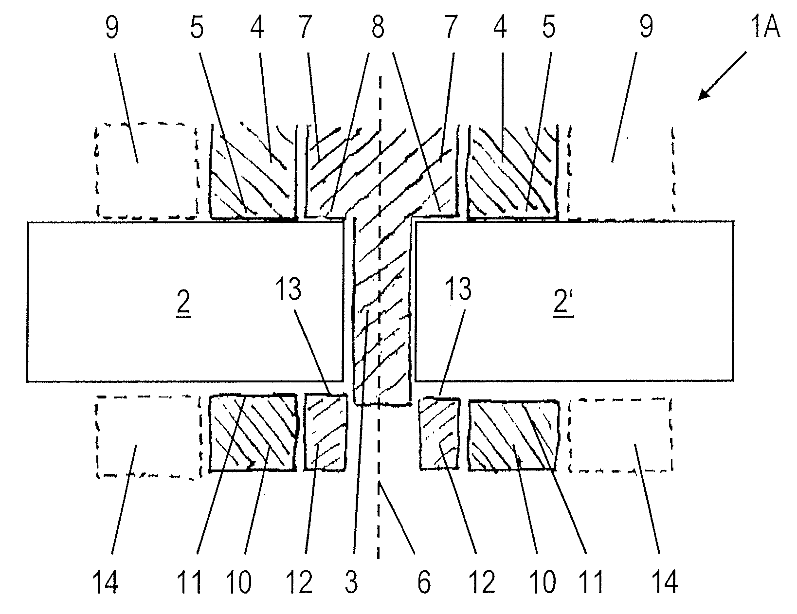
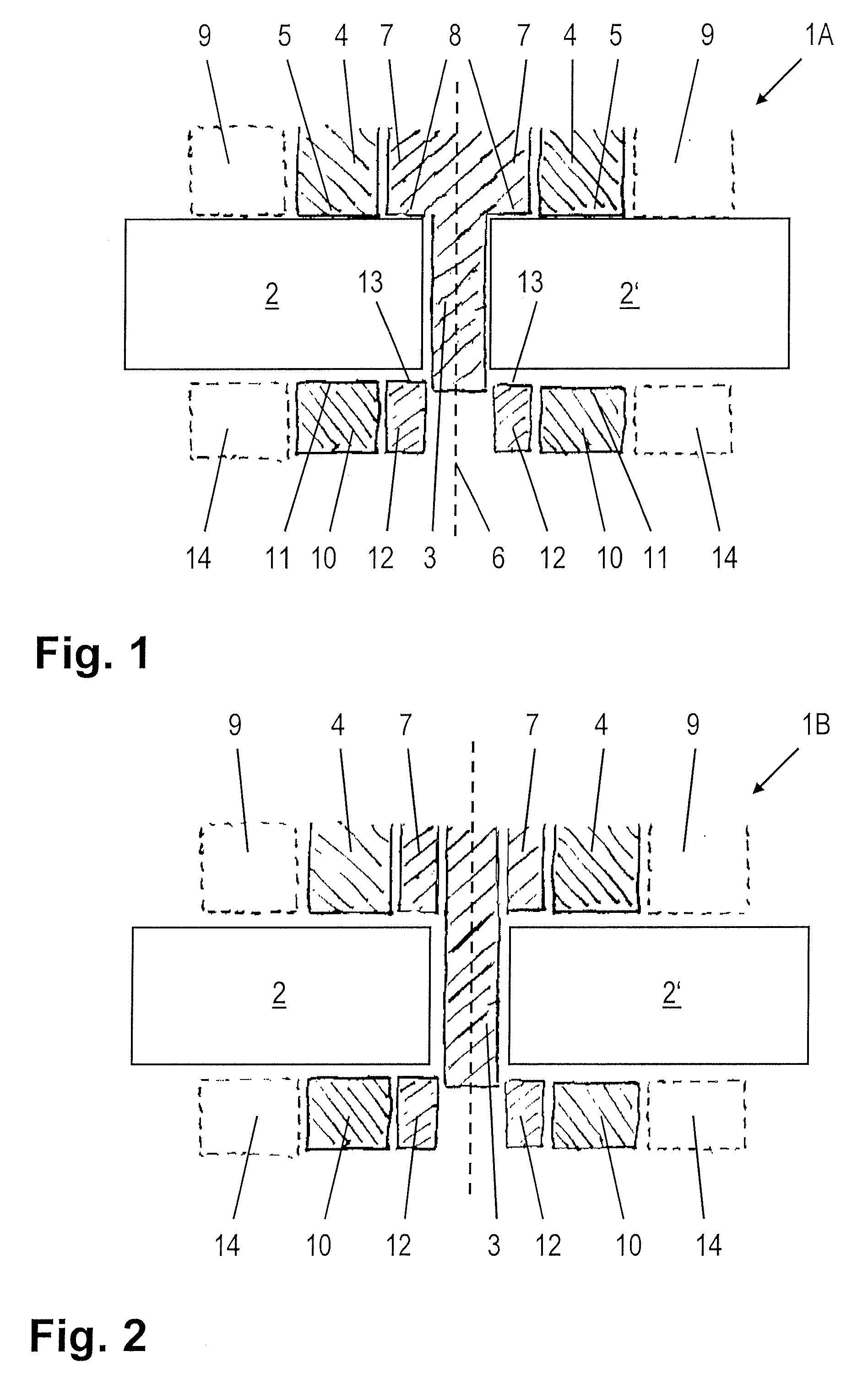
[0039]FIG. 1 illustrates the present invention. The apparatus 1A for friction stir welding, which can be guided for example along the joint along which two workpieces 2, 2′ bear against one another, comprises a pin 3 and a first friction surface segment 4, the first friction surface segment 4 being designed in the form of a circular ring. The pin 3 and the first friction surface segment 4 are rotationally driven about a common axis of rotation 6. In this context, it is on the one hand conceivable to provide separate drives for the pin 3 and the first friction surface segment 4. However, it is also possible to use a first drive jointly for both the pin 3 and the first friction surface segment 4.

[0040] The first friction surface segment 4 has a first friction surface 5 for resting on the workpieces 2, 2′. Furthermore, there is a first inner segment 7, which is joined to the pin 3 and is surrounded by the first friction surface segment 4, the first friction surface segment 4 being rota...

second embodiment

[0048] The second embodiment according to the present invention, which is illustrated in FIG. 2, differs from the embodiment illustrated in FIG. 1 by virtue of the fact that the first inner segment 7 is not fixedly joined to the pin 3, but rather the pin 3 is displaceable linearly along the axis of rotation 6 in the direction in which the pin extends. Furthermore, the first friction surface segment 4 is displaceable in the direction in which the pin 3 extends and can in particular be moved away from the workpieces 2, 2′, so that the apparatus according to the invention can be used to carry out what is known as “spot welding”. In this case, the pin 3, which does not initially protrude beyond the first friction surface 5, is lowered, rotating, into the upper of two workpieces positioned on top of one another, while at the same time the first friction surface segment 4 is moved away from the workpieces 2, 2′, so that material which is displaced by the pin 3 can penetrate into the volum...

third embodiment

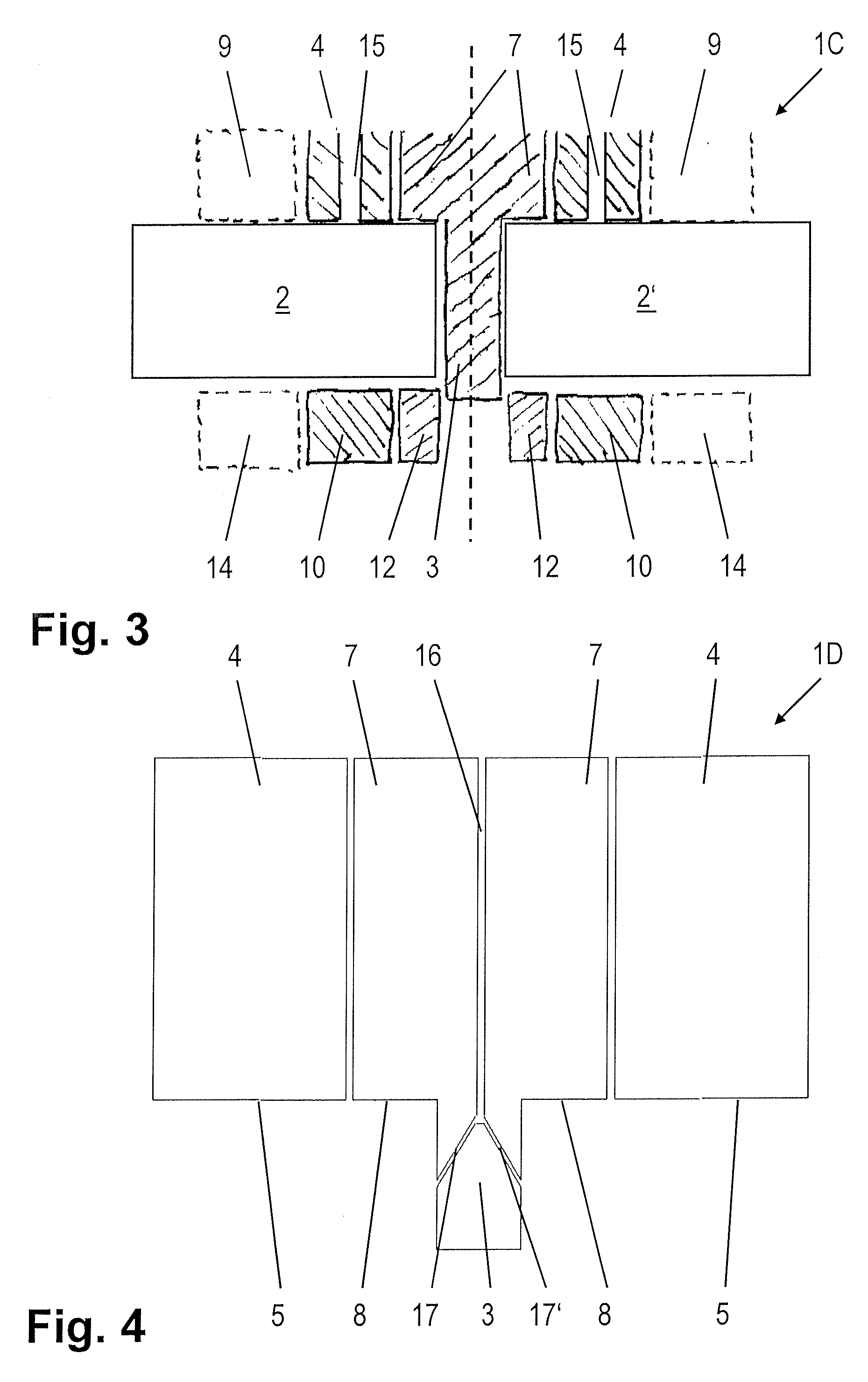
[0049] The third embodiment, shown in FIG. 3, of an apparatus 1C according to the invention differs from the first exemplary embodiment, which is illustrated in FIG. 1, by virtue of the fact that friction surface passages 15 are provided in the first friction surface segment 4, in order for a filler material to be introduced into the zone which has been plasticized by the friction with the pin 3, with the inner segment13 and with the friction surface segment 4.

[0050] Alternatively, as in the fourth exemplary embodiment, shown in FIG. 4, of an apparatus 1D, it is possible to provide a central passage in the pin 3, through which a filler material is likewise introduced into the interior of the weld seam. The apparatus 1D once again comprises a pin 3 and a first friction surface segment 4. The first friction surface segment 4 is designed in the form of a circular ring and surrounds the pin 3. In this embodiment, which is preferred in this respect, the feed device is designed as a centr...


PUM

PropertyMeasurementUnit
frictionaaaaaaaaaa
friction surfaceaaaaaaaaaa
inner frictionaaaaaaaaaa

Abstract

The invention illustrates and describes an apparatus for friction stir welding, having a pin (3) and a first friction surface segment (4), the pin (3) and the first friction surface segment (4) being rotationally driven about an axis of rotation (6), and the first friction surface segment (4) having a first friction surface (5) for resting on a workpiece (2). The object of providing a friction stir welding apparatus which can be used to better set the energy which is introduced into the workpiece by way of the friction between pin and friction surface, on the one hand, and workpiece, on the other hand, is achieved by virtue of the fact that a first inner segment (7) is provided, having a first inner friction surface (8) for resting on a workpiece (2, 2′), that the first inner segment (7) surrounds the pin (3), that the first friction surface segment (4) surrounds the first inner segment (7), and that the first friction surface segment (4) is rotationally driven independently of the first inner segment (7).

Description

RELATED APPLICATION [0001] This Application claims priority of German Application Serial No. DE 10 2005 029 882.6, filed Jun. 27, 2005, which is hereby incorporated by reference herein. BACKGROUND OF THE INVENTION [0002] 1. Field of the Invention [0003] The present invention relates to an apparatus for friction stir welding, having a pin and a first friction surface segment, the pin and the first friction surface segment being rotationally driven about an axis of rotation, and the first friction surface segment having a first friction surface for resting on a workpiece. [0004] 2. Discussion of Prior Art [0005] The principle of friction welding has been known from the prior art for many years and involves a relative movement between two workpieces while these workpieces are being pressed against one another along a contact line. The friction generates a plasticized zone along the contact line, so that when the relative movement comes to a stop the plasticized region can solidify and ...

Claims


Application Information

Patent Timeline
Patent Type & Authority Applications(United States)
IPC IPC(8): B23K20/12
CPCB23K20/1255B23K20/128B23K20/126
Inventor ZETTLER, RUDOLPHSHEIKHI, SHAHRAMBEYER, MATHIASDOS SANTOS, JORGE F.ROOS, ARNELOITZ, HENRY
Owner GKSS FORSCHUNGSZENTRUM GEESTHACHT GMBH
Why Eureka
Try Eureka