antenna

a wireless device and antenna technology, applied in the direction of antennas, antenna details, antennas with plural divergent straight elements, etc., can solve the problems of antenna malfunction, mechanical vulnerability and unreliable electrical contact between feed and grounded arm, and antenna performance could be greatly degraded by metal portion of the device housing

Inactive Publication Date: 2015-03-12
MEDIATEK INC
View PDF2 Cites 25 Cited by
  • Summary
  • Abstract
  • Description
  • Claims
  • Application Information

AI Technical Summary

Benefits of technology

The present invention offers an improved design for electronic devices that use antennas. This new design uses internal structure within the device's housing to create a ground component which can be fed without physically touching it. This eliminates certain drawbacks associated with traditional methods of connecting the ground component.

Problems solved by technology

The technical problem addressed in this patent is the degraded performance of antennas in wireless devices that have metal portions in their housing. The metal can interfere with the proper functioning of the antenna, leading to malfunctions. The prior art solution of using a gapped metal ring enclosing a rim of the housing as an arm of an inverted F antenna is unreliable due to the vulnerable electrically conductive contact between the feed and the grounded arm.

Method used


Image

  • antenna
  • antenna
  • antenna

Examples


Embodiment Construction

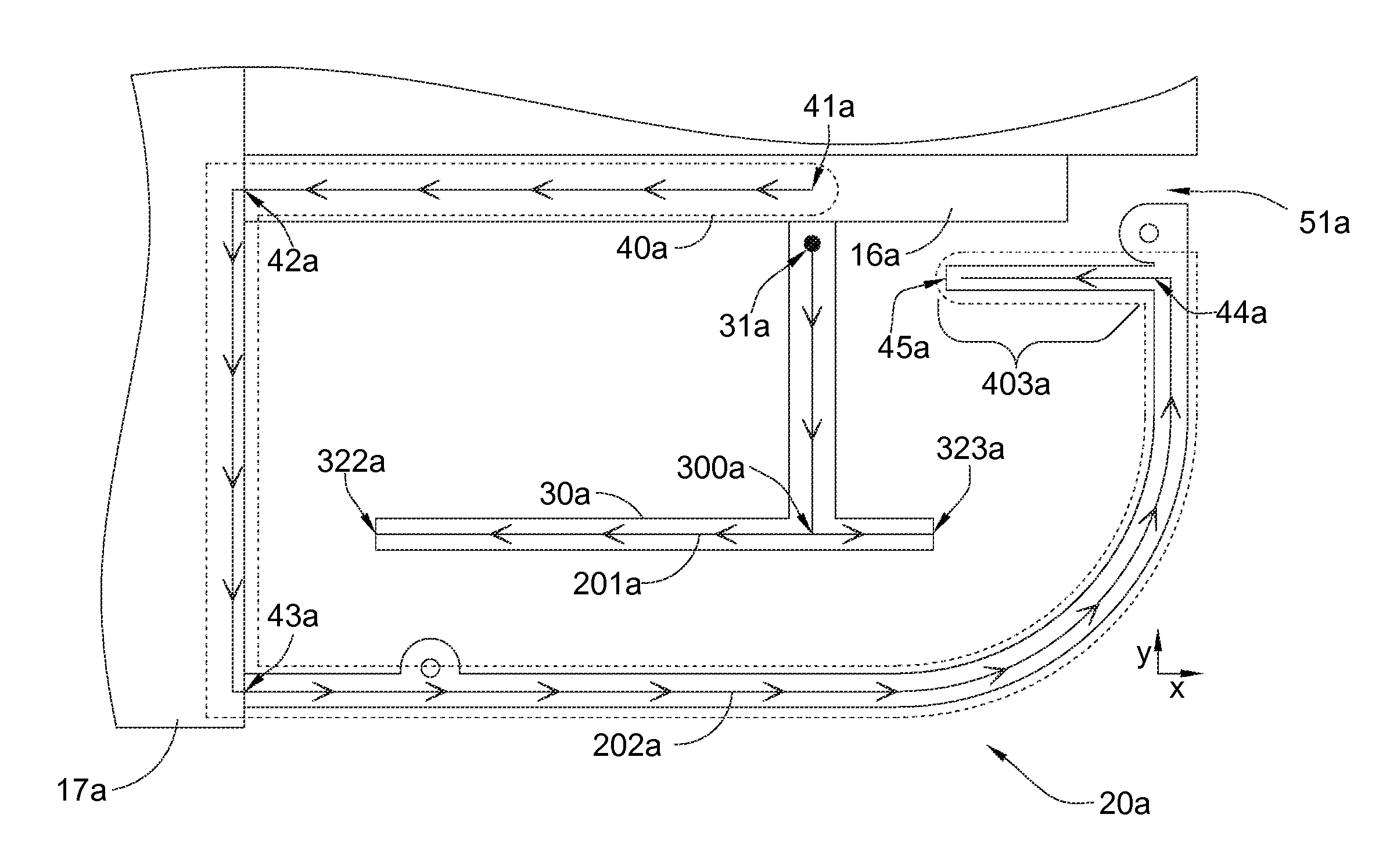
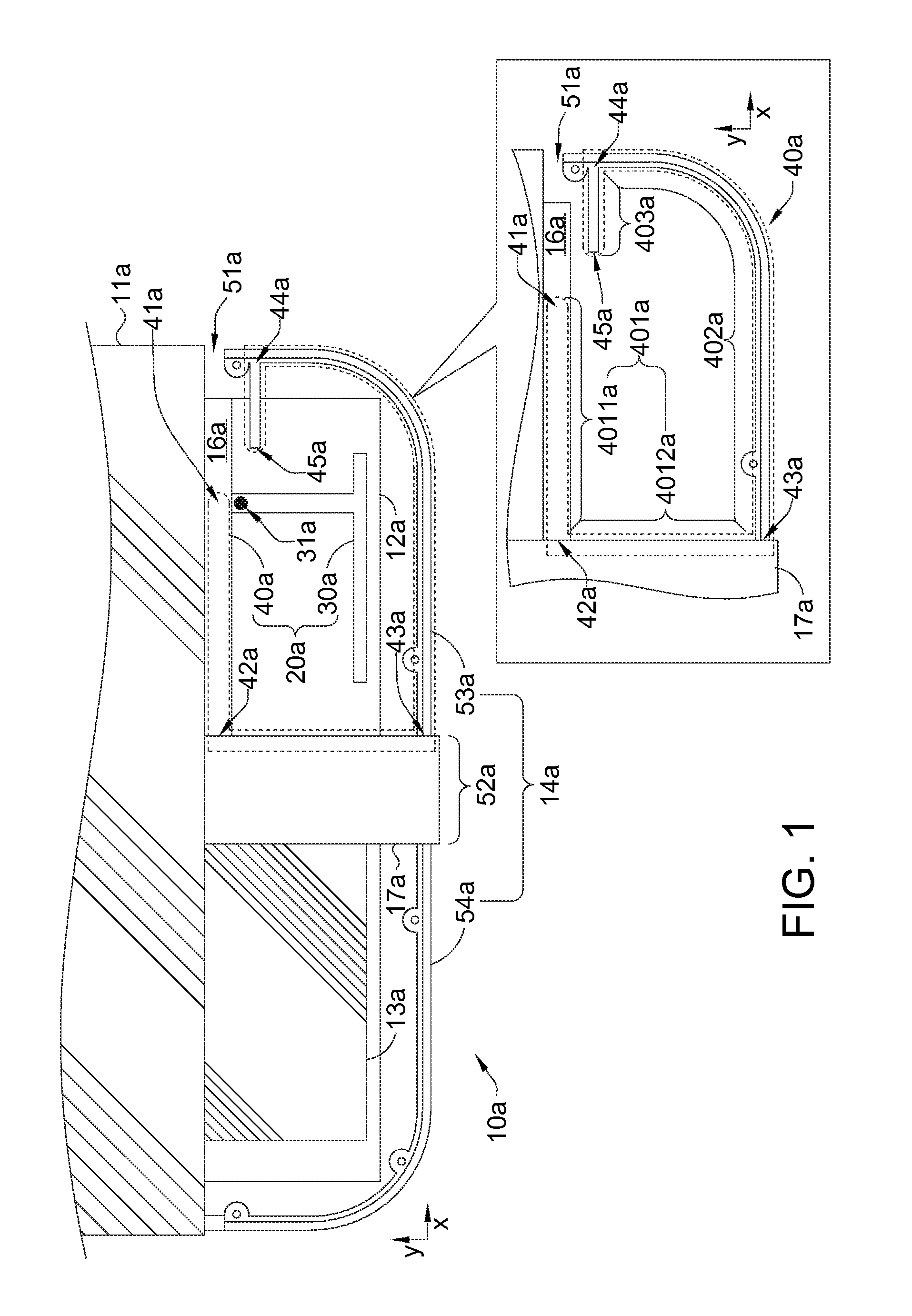
[0034]According to an embodiment of the invention, please refer to FIG. 1 illustrating an antenna 20a for a wireless device 10a. In addition to the antenna 20a embedded inside the device 10a, the device 10a may also include a circuit board 12a, a metal part 14a, and elements 11a, 13a and 17a. The metal part 14a may extend along surface(s) of the device 10; for example, the metal part 14a may include a portion extending along side surface(s) of the device 10a, such as a portion of a metal ring surrounding rim of the device 10a; and / or, the metal part 14 may include a portion extending along (flat or curved) front and / or back surface(s) of the device 10a, e.g., a portion of a back plate of the device 10a, and / or a decorative belt of a front plate of the device 10a. The metal part 14a may be gapped by a gap 51a, and may include an opening 52a between two segments 53a and 54a of the metal part 14a. In the embodiment of FIG. 1, the gap 51a and the opening 52a can be at different side sur...


PUM


Abstract

The invention provides an antenna for a wireless device, e.g., a cellular phone for wireless mobile telecommunication. The antenna includes a conductive feed strip and a conductive ground component. The ground component is for connecting a ground voltage, and comprises a portion along a surface of the device. The feed strip has a feed port for relaying a feed signal, and does not physically contact the ground component, so as to feed the ground component by noncontact electrical coupling, instead of physical contact.

Description


Claims


Application Information

Patent Timeline
Owner MEDIATEK INC
Why Eureka
Try Eureka