Many consumers struggle to find a convenient and aesthetically pleasing location for such components in the
bedroom.
This exudes a cluttered and disorganized appearance that is not aesthetically pleasing.
However, some other consumers would prefer to maximize the enclosed storage space within the furniture (i.e., drawers and cabinets) and, therefore, not have any open spaces for storing electronic components.
This can leave a cluttered look on top of the nightstand, and it takes away from space that may otherwise be used for items such as lamps and photographs.
Additionally, when valuable electronic devices are laid on top of a nightstand, for example, they are prone to
spillage of beverages that the
consumer may have set on the nightstand.
If consumers choose to charge the devices while in a drawer of the nightstand, the devices are less accessible and the charger cords typically hang out of the drawer as they extend to the wall outlet, thereby producing an undesirable visual effect and leaving the cords subject to damage if the
consumer inadvertently attempts to fully close the drawer.
The
furniture industry has addressed the issue of electronic device storage in the bedroom in a very ineffective way.
Yet, those options are fraught with issues, as explained below.
Though the
open cavity provides for storage and organization of electronic components, it creates a problem if the
consumer does not have a need for storing electronic components, such as in the bedroom.
In that case, the
open cavity merely becomes a
dust collector and wasted space which could have otherwise been used for covered storage, such as drawers for clothes.
Some other prior art case pieces of furniture include a cabinet with a glass door for storing electronic components, but these are not typically seen in bedroom furniture, especially if there is no need for storing components.
Therefore, glass
doors are not an aesthetically desired option for many consumers, and the functionality is pre-determined for use with storing components because most consumers are unwilling to store clothing in a glass-faced cabinet.
The drop-down door becomes an unsightly protrusion from the furniture when it is down.
Also, such drop-down
doors do not enable the consumer to have true drawer-type storage space because the drawer is not able to be pulled from and retracted into the case piece.
While this option provides dual functionality, the typical six to eight inch protrusion of the drop down door is unsightly, and such protrusion could cause bodily injury, which raises significant product liability concerns for the manufacturers.
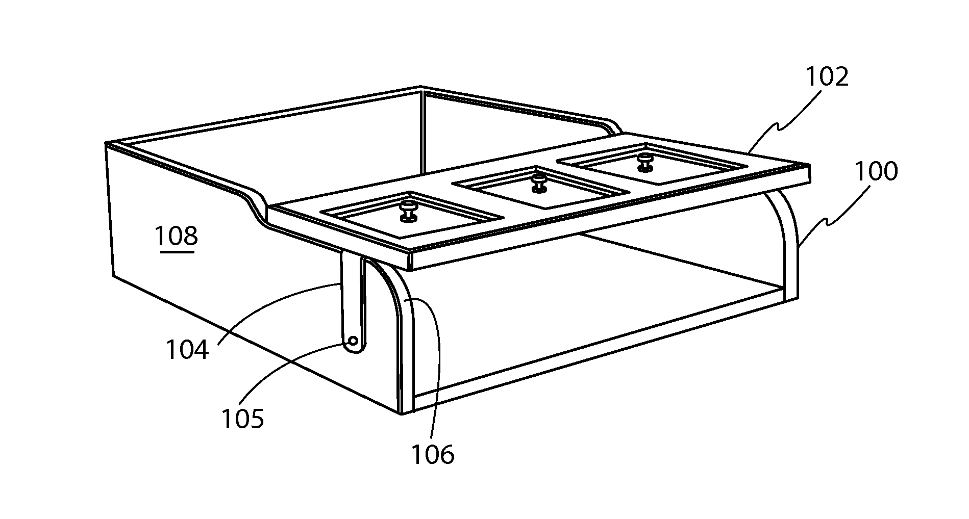
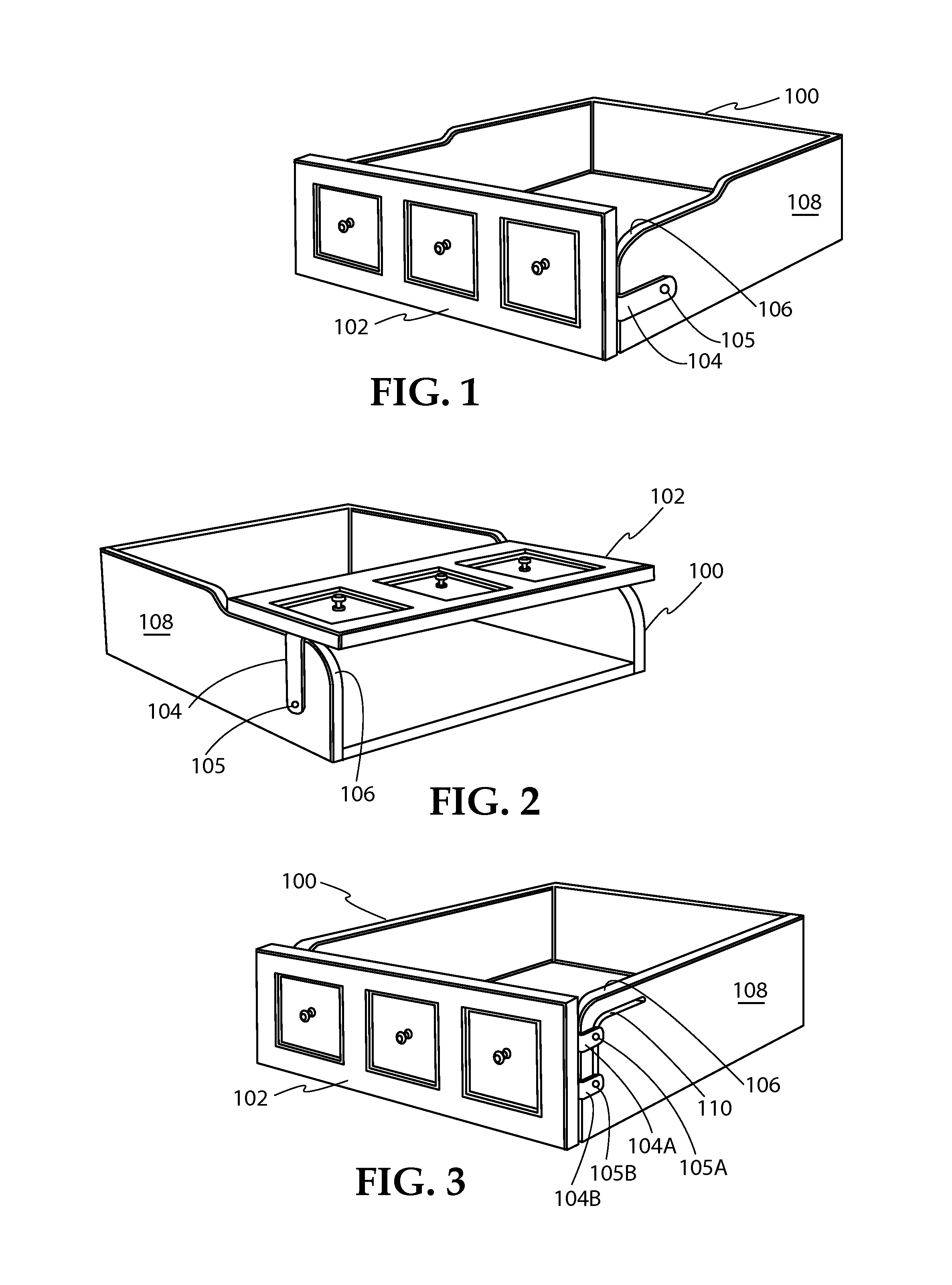
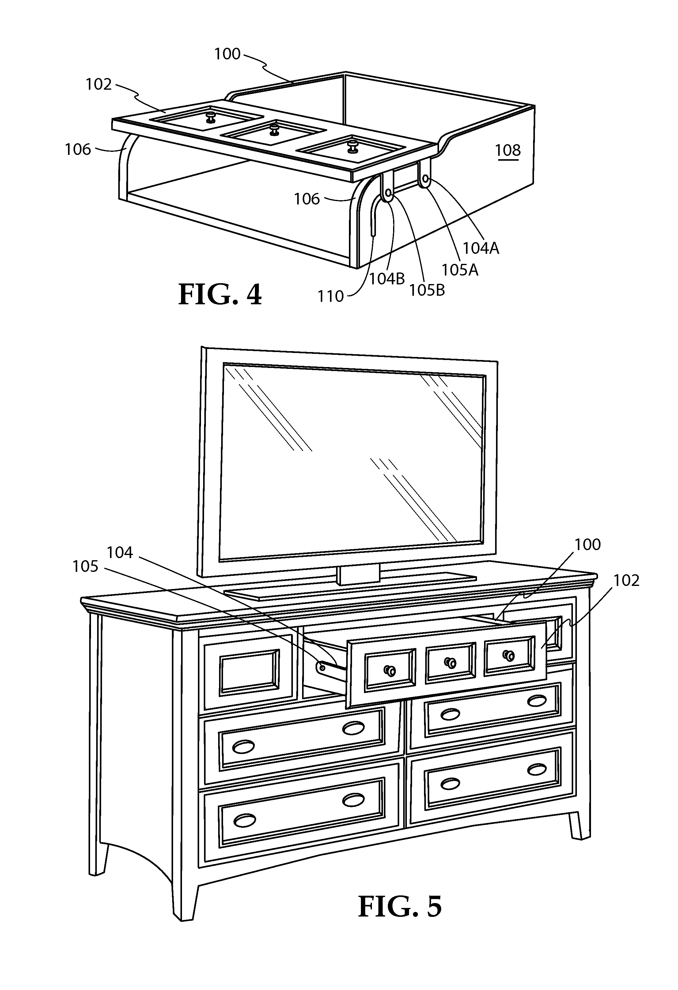
None of the foregoing options that are presently available in the marketplace address the need for a safe and aesthetically pleasing item of furniture having a drawer that can function as an extendible drawer that provides covered storage space or an
open cavity for storage of electronic components.
Thus, furniture manufacturers and retailers currently have no way for marketing the same items of furniture to both types of consumers—namely, those wanting open media shelves and those wanting maximized covered storage space for clothing, et cetera.
It is not practical, nor does it make economic sense for the retailer to stock the same piece of furniture made in two different ways.

