Coordinate measurement machine with distance meter and camera to determine dimensions within camera images

a distance meter and coordinate measuring technology, applied in the field of coordinate measuring machines, can solve the problems of relatively difficult use of measurement installations and high cos

Active Publication Date: 2015-03-19
FARO TECH INC
View PDF9 Cites 56 Cited by
  • Summary
  • Abstract
  • Description
  • Claims
  • Application Information

AI Technical Summary

Benefits of technology

[0007]In accordance with one embodiment of the invention, a three-dimensional (3D) measuring device includes an articulated arm coordinate measurement machine (AACMM), the AACMM including a base and a manually positionable arm portion having opposed first and second ends, the arm portion including a plurality of connected arm segments, each arm segment including at least one position transducer for producing a position signal, the first end attached to the base, a camera coupled to the second end, a non-contact 3D measurement device coupled to the second end, the noncontact 3D measurement device having a light source, the noncontact 3D measurement device configured to determine a distance to an object point based at least in part on the speed of light in air, and an electronic circuit which receives the position signal from the at least one position transducer and provides data corresponding to a position of the camera and the non-contact 3D measurement device; a processor system including at least one of an AACMM processor, an external computer, and a cloud computer configured for remote access, wherein the processor system is responsive to executable instructions which when executed by the processor system is operable to: cause the light source to send a first beam of light to a first object point; cause the noncontact 3D measurement device to receive a first reflected light and determine a first distance to the first object point in response, the first reflected light being a portion of the first beam of light reflected by the first object point; determine an angle of the first beam of light relative to the AACMM based at least in part on first position signals from the transducers; determine first 3D coordinates of the first object point based at least in part on the first distance and a first angle of the first beam of light relative to the AACMM; cause the camera to obtain a first 2D image of a first surface, the first 2D image having a first spot of light caused by the first beam of light intersecting the first surface at the first object point; and associate the first 3D coordinates to the first spot of light.

Problems solved by technology

Portable AACMMs represent a vast improvement over known stationary or fixed, cost-intensive and relatively difficult to use measurement installations, particularly in the amount of time it takes to perform dimensional measurements of relatively complex parts.

Method used


Image

  • Coordinate measurement machine with distance meter and camera to determine dimensions within camera images
  • Coordinate measurement machine with distance meter and camera to determine dimensions within camera images
  • Coordinate measurement machine with distance meter and camera to determine dimensions within camera images

Examples


Embodiment Construction

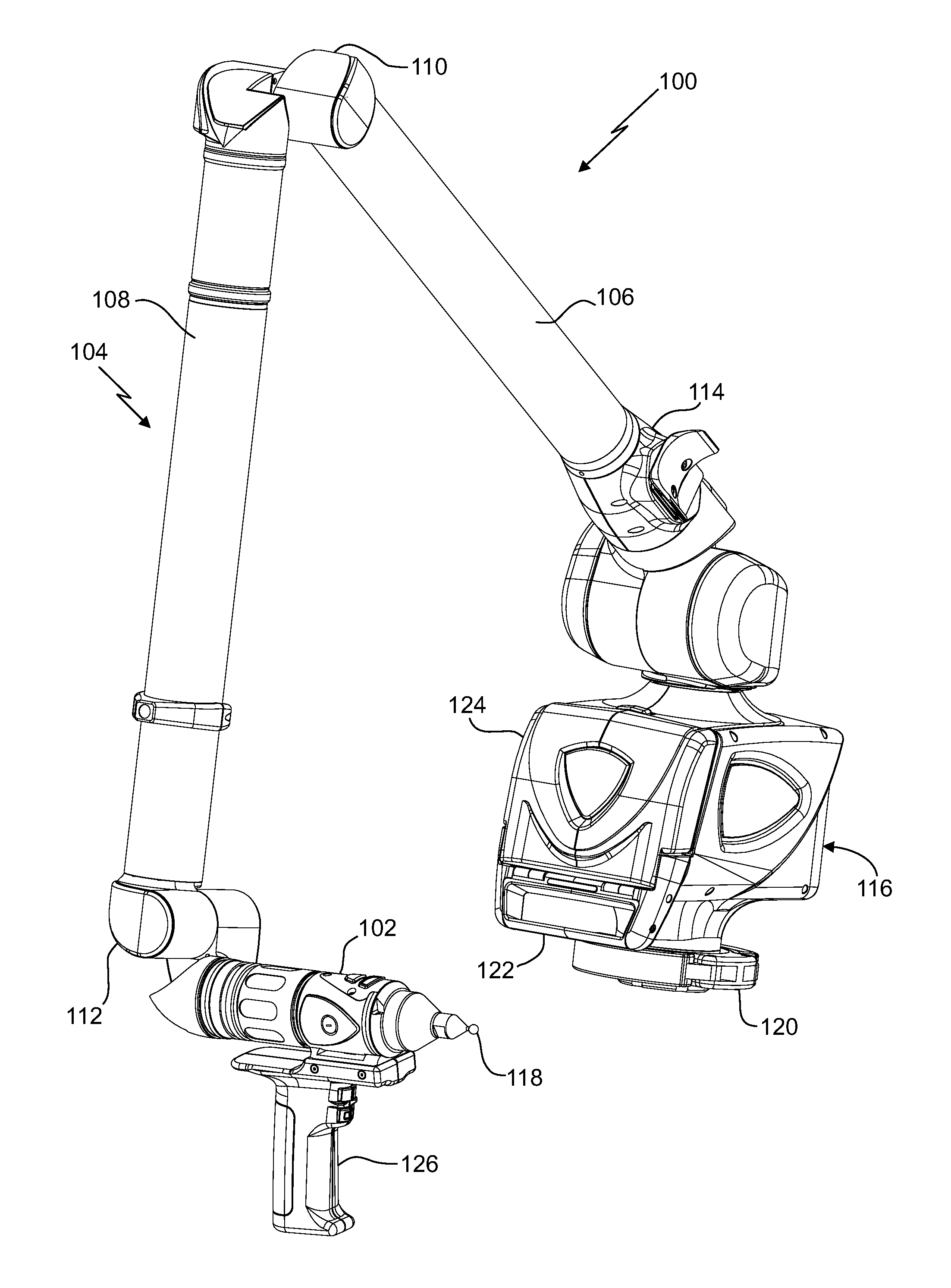
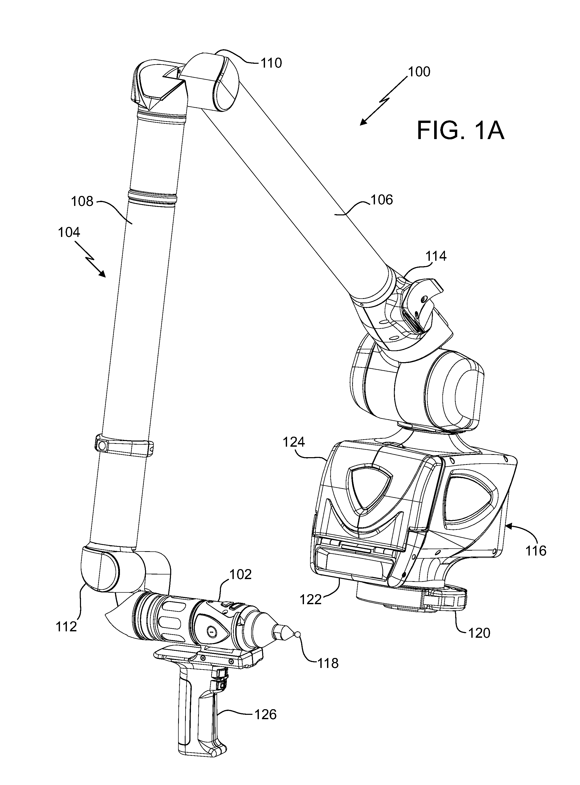
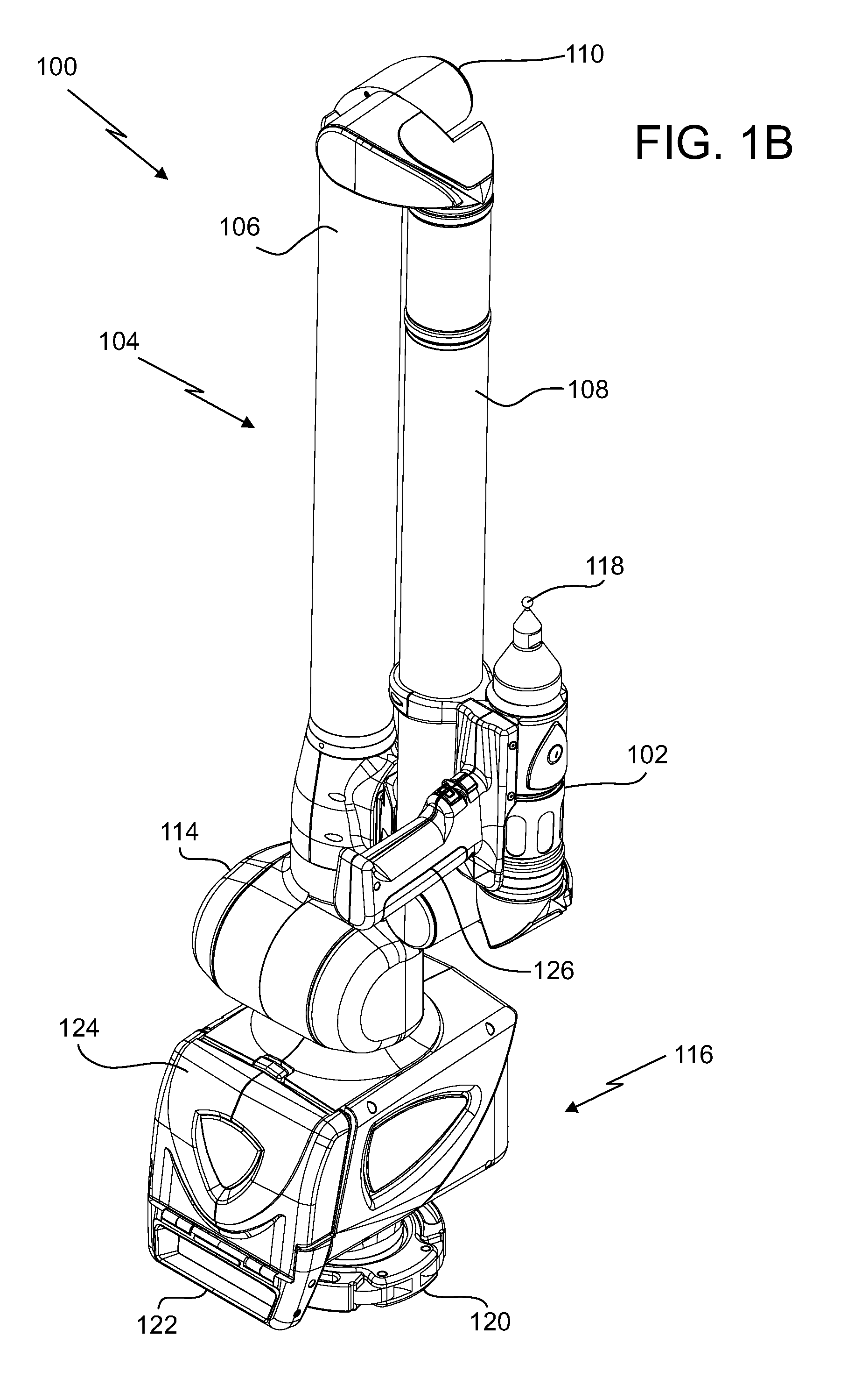
[0024]Portable articulated arm coordinate measuring machines (“AACMM”) are used in a variety of applications to obtain measurements of objects. Embodiments of the present invention provide advantages in allowing an operator to easily and quickly couple accessory devices to a probe end of the AACMM that use structured light to provide for the non-contact measurement of a three-dimensional object. Embodiments of the present invention provide further advantages in providing for communicating data representing a distance to an object measured by the accessory. Embodiments of the present invention provide still further advantages in providing power and data communications to a removable accessory without having external connections or wiring.

[0025]FIGS. 1A and 1B illustrate, in perspective, an AACMM 100 according to various embodiments of the present invention, an articulated arm being one type of coordinate measuring machine. As shown in FIGS. 1A and 1B, the exemplary AACMM 100 may comp...


PUM


Abstract

An articulated arm coordinate measurement machine (AACMM) that includes a noncontact 3D measurement device, position transducers, a camera, and a processor operable to project a spot of light to an object point, to measure first 3D coordinates of the object point based on readings of the noncontact 3D measurement device and the position transducers, to capture the spot of light with the camera in a camera image, and to attribute the first 3D coordinates to the spot of light in the camera image.

Description

CROSS-REFERENCE TO RELATED APPLICATIONS[0001]The present application is a continuation-in-part of U.S. patent application Ser. No. 14 / 223,067, filed Mar. 24, 2014, which is a continuation-in-part of U.S. patent application Ser. No. 13 / 524,028, filed Jun. 15, 2012, now U.S. Pat. No. 8,677,643, and claims the benefit of U.S. Provisional Patent Application No. 61 / 296,555, filed Jan. 20, 2010, U.S. Provisional Patent Application No. 61 / 355,279, filed Jun. 16, 2010, and U.S. Provisional Patent Application No. 61 / 351,347, filed on Jun. 4, 2010. The present application is also a continuation-in-part of PCT Application No. PCT / U.S. Ser. No. 13 / 040,321 filed on May 9, 2013. The contents of all of the above are hereby incorporated by reference in their entirety.BACKGROUND[0002]The present disclosure relates to a coordinate measuring machine, and more particularly to a portable articulated arm coordinate measuring machine having a probe end to which a camera and a distance meter are attached a...

Claims


Application Information

Patent Timeline
Patent Type & Authority Applications(United States)
IPC IPC(8): G01B5/012G01B11/00
CPCG01B5/012G01B21/047G01B11/007G01B5/008G01B11/002G01B11/005G01B2210/58G05B19/401G05B2219/37193G05B2219/40233G05B2219/40555G05B2219/45061
Inventor BRIDGES, ROBERT E.PARKER, DAVID H.
Owner FARO TECH INC
Why Eureka
Try Eureka