Camera angle adjustable device and the method of handling the article

a technology which is applied in the field of adjustable device and camera angle angle adjustment device, can solve the problems of direct or indirect increase of circuit design complexity, increase of production cost, and increase of volume occupied by electronic devices, so as to reduce space and cost, simplify circuit design, and reduce the number of additional camera modules.

Inactive Publication Date: 2015-03-19
VI TAI TECH
View PDF5 Cites 13 Cited by
  • Summary
  • Abstract
  • Description
  • Claims
  • Application Information

AI Technical Summary

Benefits of technology

[0008]The objective of the instant disclosure is to provide a camera angle adjustable device and a method for adjusting a camera angle to minimize the additional camera module and the number of power supplies in the conventional two-directional camera in the portable electronic devices in order to reduce space and costs, as well as simplifying circuit design. In order to achieve the aforementioned objectives, according to an embodiment of the instant disclosure, a camera angle adjustable device is provided, the camera angle adjustable device comprising a base, a camera module, a reflective mirror structure, and a driver. The base has a first surface, a second surface, a front side and a back side. The camera module is disposed on a side of the first surface normal to the front side and the back side. The reflective mirror structure includes a frame and at least one mirror body. The frame is pivotally disposed on the first surface. The at least one mirror body is arranged in the frame. The at least one mirror body selectively corresponds to the front side or the back side by rotating the frame. The driver is disposed on the second surface, and the driver is engaged to the frame to drive rotations of the reflective mirror structure.
[0011]In summary, a single lens camera module can capture images or video in front or behind the camera angle adjustable device in the first embodiment, without having to provide different camera modules and power supplies. The camera angle adjustable device of the present disclosure reduces production costs and space, simplifies circuit and image processing software designs, and does not need to calibrate image quality of two camera modules having different resolutions, thus providing identical high resolution imaging quality in front of or behind the camera modules.
[0012]In the second embodiment, the frame of the reflective mirror structure has two mirror bodies arranged with an angle therebetween. The two mirror bodies can be separately arranged to face either the forward or rearward photographic windows, such that only a slight angle adjustment of the reflective mirror structure is required when adjusting the photographic windows. As a result, the camera angle adjustable device of the second embodiment can provide the same effects with a relatively smaller overall volume and thinner with respect to the camera angle adjustable device of the first embodiment. Moreover, the structure design of camera angle adjustable device is also simplified.

Problems solved by technology

Although the conventional technique allows users to shoot in two directions, since two independent lens modules and power supply systems are required, production costs increase, the volume occupied by the electronic devices increase, and the complexity of the circuit design directly or indirectly increase.
In addition, forward and rearward photographic modules typically display different resolutions in which one resolution typically suffers.
In general, the resolution of the rearward photographic module is much poorer than the forward photographic module, thus, the image quality in many photographic modules on portable electronic devices for capturing an image with a self-timer, is generally poor.

Method used


Image

  • Camera angle adjustable device and the method of handling the article
  • Camera angle adjustable device and the method of handling the article
  • Camera angle adjustable device and the method of handling the article

Examples


first embodiment

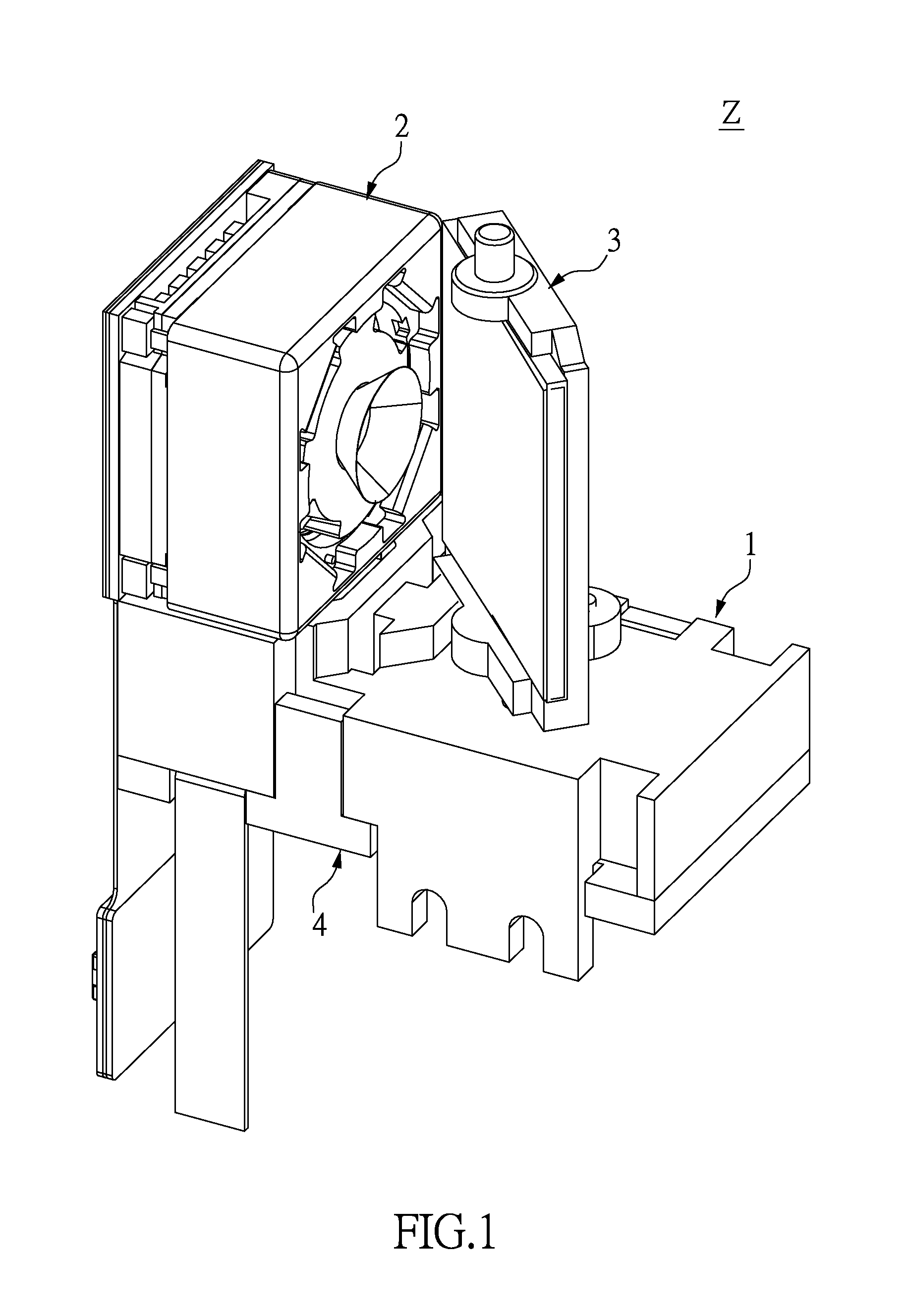
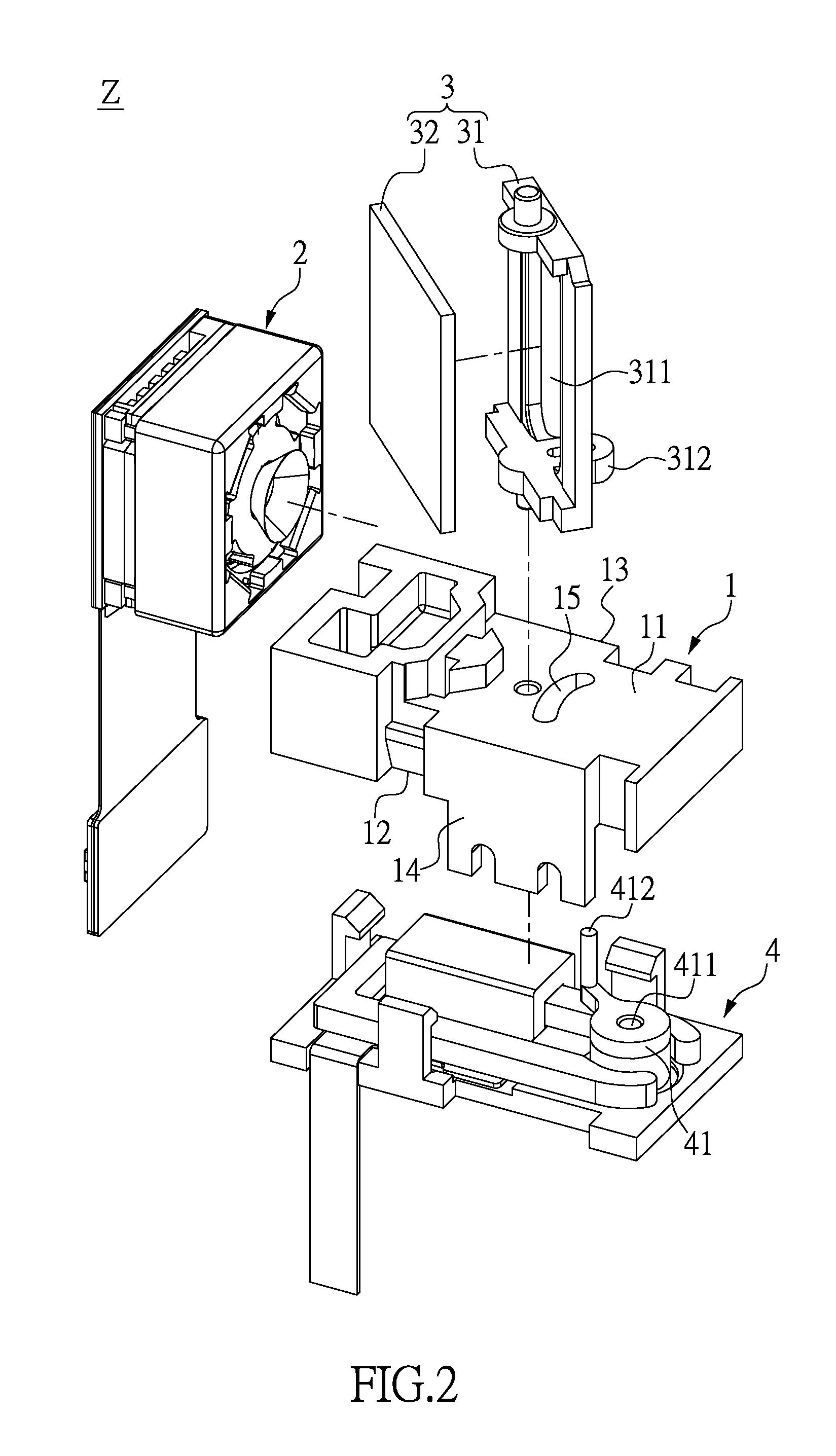
[0026]Please refer to FIGS. 1 and 2, in which FIG. 1 is an assembled view and FIG. 2 is an exploded view of a camera angle adjustable device in accordance with a first embodiment of the instant disclosure. The instant disclosure provides a camera angle adjustable device Z, which includes a base 1, a camera module 2, a reflective mirror structure 3, and a drive 4. The camera module 2 and the reflective mirror structure 3 are disposed on a side of the base 1, whereas the driver 4 is disposed on another side of the base 1 and connected to the reflective mirror structure 3 in order to rotate the reflective mirror structure 3. Further structural characteristics and configurations between each element are disclosed below.

[0027]Please refer to FIGS. 2 to 4A, in which FIG. 3 is another exploded view of the camera angle adjustable device in accordance with the first embodiment of the instant disclosure. The base 1 has a first surface 11, a second surface 12, a front end 13, and a back end 14...

second embodiment

[0038]Please refer to FIGS. 5 and 6. FIG. 5 is an assembled view of the camera angle adjustable device in accordance with a second embodiment of the instant disclosure, whereas FIG. 6 is an exploded view of the camera angle adjustable device in accordance with the second embodiment. The instant embodiment differs from the previous embodiment in that the frame 31 of the reflective mirror structure 3 includes a frame body 313 and a base seat 314, as well as two mirror bodies 32. The frame body 313 and the base seat 314 are connected to each other to define a second receiving portion 315 and a third receiving portion 316. The mirror bodies 32 are respectively inserted in the second and the third receiving portions 315, 316. Furthermore, the frame body 313 of the frame 31 resembles a triangular prism. When the mirror bodies 32 are assembled, an angle θ (as shown in FIG. 7A), an acute angle, exists between the mirror bodies 32 of less than 90 degrees.

[0039]Please refer to FIG. 7A as a sc...

third embodiment

[0042]Please refer to FIGS. 6 to 8. FIG. 8 is a partial exploded view of the camera angle adjustable device in accordance with a third embodiment of the instant disclosure. The instant embodiment differs from the previous embodiments in that the base 1 of the instant embodiment has an auxiliary wall surface 16 arranged thereon. The auxiliary wall surface 16 has a top portion. The top portion of the auxiliary wall surface 16 has a fixing base 161 arranged thereon. The auxiliary wall surface 16 is disposed on a side of the first surface 11 corresponding to the camera module 2. As a result, the auxiliary wall surface 16 can be used to assist rotation of the reflective mirror structure and prevent the reflective mirror structure 3 from excessive rotation. The fixing base 161 can fix the reflective mirror structure 3 from above.

[0043]More specifically, the first surface 11 and the fixing base 161 of the base 1 each have a first pivotable portion 17 arranged thereon. The frame 31 has an u...


PUM


Abstract

The instant disclosure relates to a camera angle adjustable device. The camera angle adjustable device includes a base, a camera module, a reflective mirror structure and a driver. The base has a first surface, a second surface, a front side and a back side. The camera module is disposed on one side perpendicular to the front side and the back side of the first surface. The reflective mirror structure includes a frame and a mirror body, wherein the frame is pivotally connected to the first surface, the mirror body is mounted on the frame, and the mirror body selectively corresponds to one of the front side and the back side. The driver is mounted on the second surface and connected to the reflective mirror structure in order to drive the reflective mirror structure. A method for adjustable the camera angle is also provided.

Description

BACKGROUND OF THE INVENTION[0001]1. Field of the Invention[0002]The instant disclosure relates to a camera angle adjustable device and a method for adjusting a camera angle; in particular, to a camera angle adjustable device and a method for adjusting a camera angle for a portable electronic device.[0003]2. Description of Related Art[0004]As modern science and technology develops, the demand for photographic capabilities in portable electronic devices, such as tablet computers and mobile phones, significantly increases. Moreover, front facing and rear facing photographic shooting has been further developed, such that users can shoot in front of or behind the electronic device.[0005]Conventional portable electronic device may include a two- directional system which uses two different lens modules to provide the forward and rearward shooting. Users can switch between the two lens modules via software control to achieve two-directional shooting.[0006]Although the conventional technique...

Claims


Application Information

Patent Timeline
Patent Type & Authority Applications(United States)
IPC IPC(8): H04N5/232H04N5/225G02B7/182
CPCH04N5/23296H04N5/2254G02B7/1821G03B5/00G02B26/0816G03B17/17H04N23/55H04N23/58H04N23/69G03B15/12
Inventor LO, CHI-WUWANG, CHAO-HSILIU, KAO-CHI
Owner VI TAI TECH
Why Eureka
Try Eureka