Switching lens for display apparatus and method for manufacturing the same

a technology of switching lens and display apparatus, which is applied in the direction of lenses, static indicating devices, instruments, etc., can solve the problems of defective molecular orientation of liquid crystals, large problems, and large deviation of the thickness of the alignment film formed, and achieve the desired optical properties.

Inactive Publication Date: 2015-03-19
KOLON IND INC
View PDF1 Cites 8 Cited by
  • Summary
  • Abstract
  • Description
  • Claims
  • Application Information

AI Technical Summary

Benefits of technology

[0021]According to the present invention, the thickness deviation of an alignment film formed on the whole curvature surface of each lenticular pattern within a switching lens can be minimized, and thus the molecular orientation uniformity of the liquid crystals dispensed onto the alignment film can be maximized. As a result, the switching lens of the present invention can have the desired optical properties.
[0022]Other advantages of the present invention will be described below in detail together with the related technical features.

Problems solved by technology

Such curved shape of the polymer film causes lots of problems when the rubbing process is performed.
Further, a certain portion of the curvature surface of the lenticular pattern even may not be coated with the polymer solution, which causes the defective molecular orientation of the liquid crystals.
Secondly, when the polymer film is rubbed with a rubbing cloth, a portion of the structure, especially the mountain portions between the neighboring concave lens patterns, may be damaged by the rubbing cloth thereby causing the defective molecular orientation of the liquid crystals.

Method used


Image

  • Switching lens for display apparatus and method for manufacturing the same
  • Switching lens for display apparatus and method for manufacturing the same
  • Switching lens for display apparatus and method for manufacturing the same

Examples


first embodiment

[0030]Hereinafter, a switching lens according to the present invention will be described in detail with reference to the FIGS. 1 to 3.

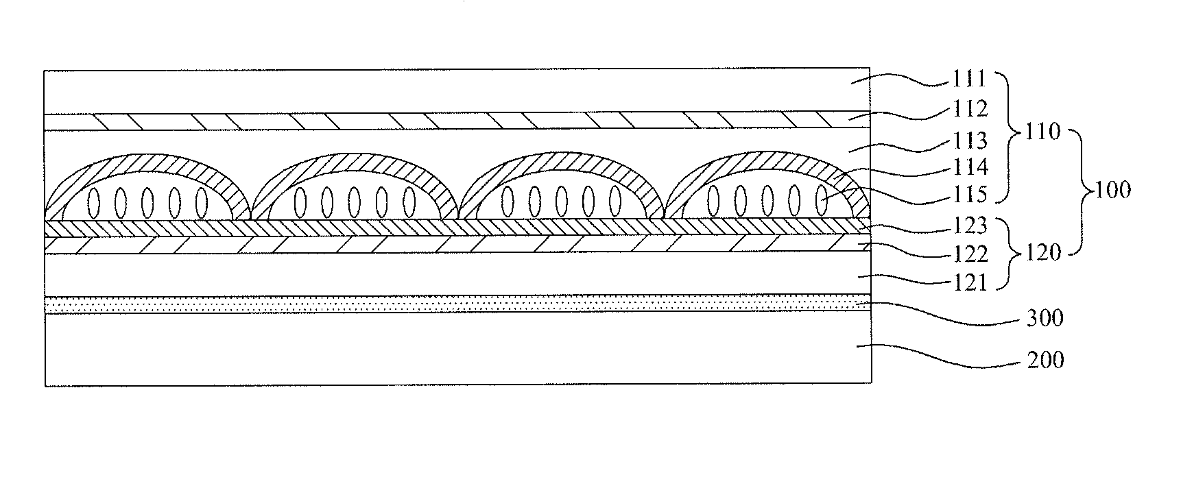
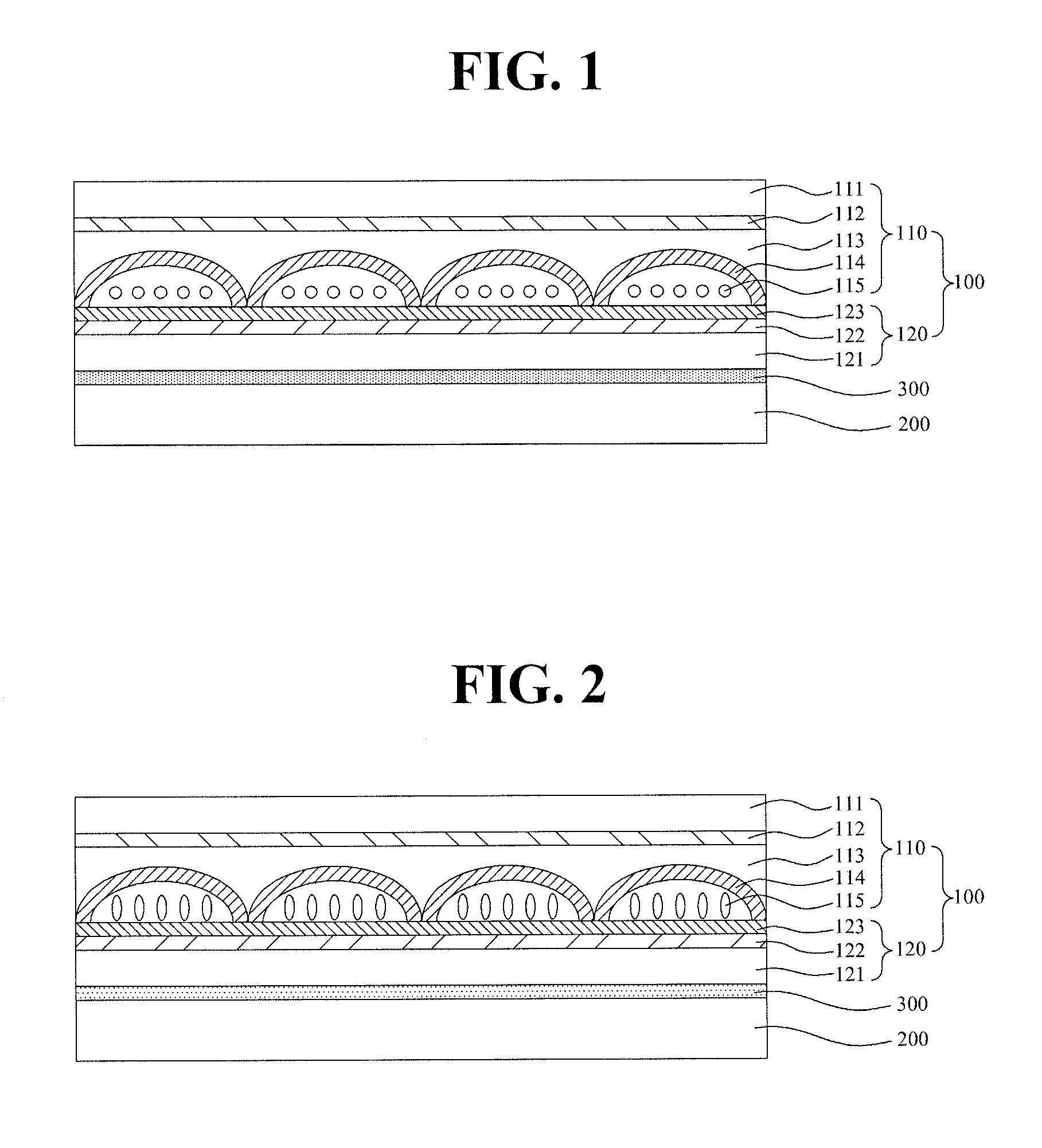
[0031]FIG. 1 and FIG. 2 are cross-sectional views respectively illustrating 2D mode state and 3D mode state of a display apparatus comprising a switching lens according to the first embodiment of the present invention.

[0032]As illustrated in FIG. 1 and FIG. 2, the display apparatus comprises a switching lens 100 according to the first embodiment of the present invention, a display panel 200, and an adhesive layer 300 between the switching lens 100 and display panel 200.

[0033]The switching lens 100 comprises an upper plate 110 and a lower plate 120, the upper and lower plates 110 and 120 being bonded together.

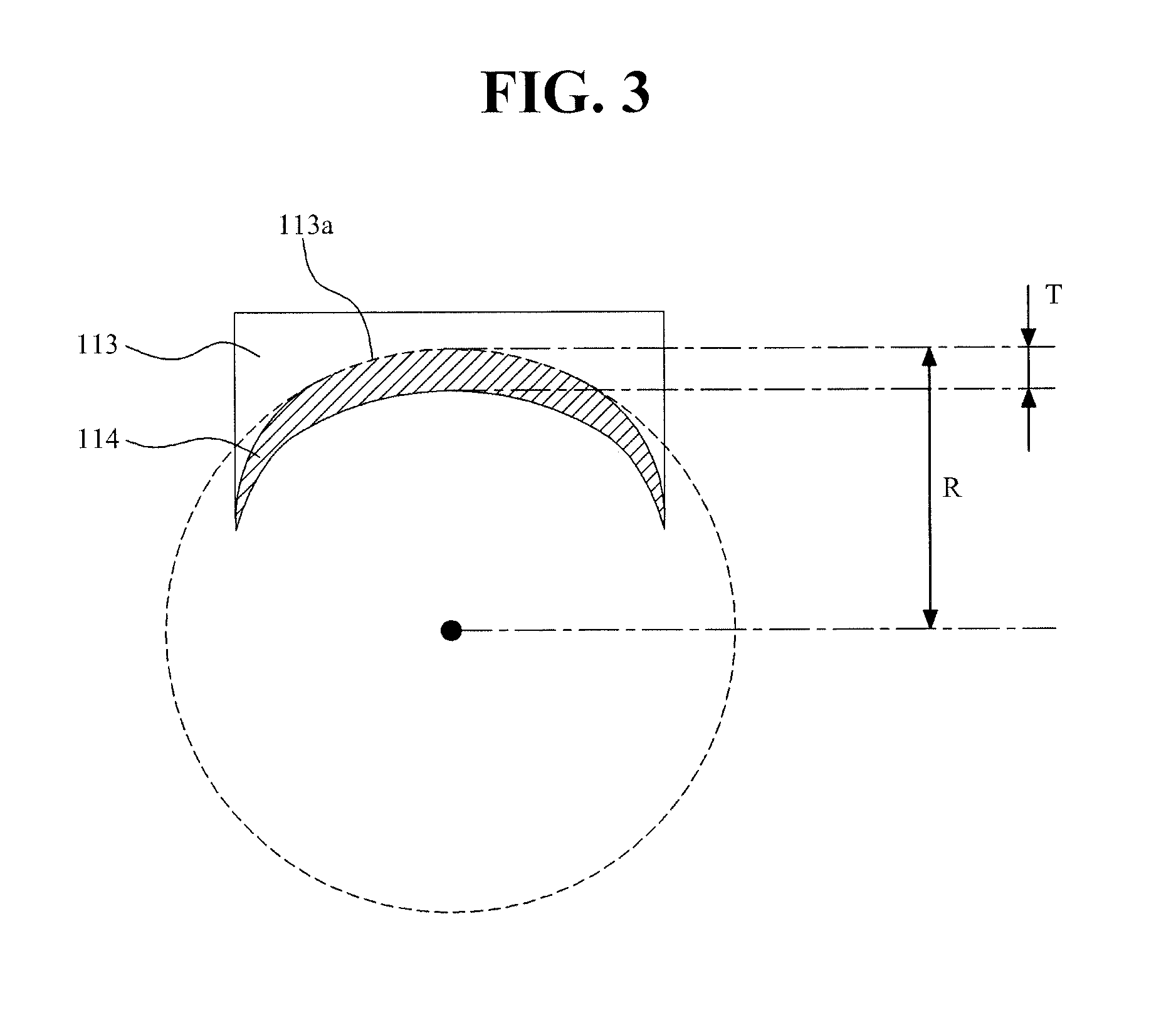
[0034]The upper plate 110 comprises a first film 111, a first transparent electrode 112 on the first film 111, a resin layer 113 on the first transparent electrode 112, a first alignment film 114 on the resin layer 113, and liquid crystals 115 on ...

second embodiment

[0044]FIG. 4 and FIG. 5 are cross-sectional views respectively illustrating 2D mode state and 3D mode state of a display apparatus comprising a switching lens according to the present invention.

[0045]As illustrated in FIG. 4 and FIG. 5, the display apparatus comprises a switching lens 100 according to the second embodiment of the present invention, a display panel 200, and an adhesive layer 300 between the switching lens 100 and display panel 200.

[0046]The switching lens 100 comprises an upper plate 110, a lower plate 120 bonded to the upper plate 110, a polarization switching unit 130, and an adhesive layer 140 between the lower plate 120 and the polarization switching unit 130.

[0047]The upper plate 110 comprises a first film 111, a resin layer 113 on the first film 111, a first alignment film 114 on the resin layer 113, and cured reactive mesogens 116 on the first alignment film 114.

[0048]The resin layer 113 has a plurality of lenticular patterns. The lenticular patterns may be cy...


PUM

PropertyMeasurementUnit
wt %aaaaaaaaaa
wt %aaaaaaaaaa
photosensitiveaaaaaaaaaa

Abstract

Disclosed are a switching lens and a method for manufacturing the same. The switching lens having liquid crystals of highly uniform orientation can be obtained by minimizing the thickness deviation of an alignment film formed on the whole curvature surface of a lenticular pattern. The switching lens of the present invention comprises a resin layer having a lenticular pattern and an alignment film on the resin layer. The alignment film covers the whole curvature surface of the lenticular pattern and has the maximum thickness equal to or less than 0.01 times the maximum radius of curvature of the lenticular pattern.

Description

TECHNICAL FIELD[0001]The present invention relates to a switching lens for a display apparatus and a method for manufacturing the same, and more particularly, to a switching lens having liquid crystals of highly uniform orientation which can be obtained by minimizing the thickness deviation of an alignment film formed on the whole curvature surface of a lenticular pattern and a method for manufacturing the same.BACKGROUND ART[0002]The principle of stereo vision with two eyes facilitates three-dimensional display of a three-dimensional image. The binocular disparity due to the two eyes which are apart from each other by about 65 mm is one of the most important factors for stereocognosy.[0003]Once the different two-dimensional images inputted through the right and left eyes respectively are transmitted to the brain, the brain combines the images together thereby reproducing the depth and reality of the original three-dimensional image. The technology creating a three-dimensional image...

Claims


Application Information

Patent Timeline
Patent Type & Authority Applications(United States)
IPC IPC(8): B29D11/00G02F1/1337G02F1/137G02B27/22G02B30/28
CPCB29D11/00009G02B27/2214G02F1/137G02F1/133723G02F1/133788G02B30/27G02B30/28G02F1/1335G02F1/1337G02B3/00
Inventor SON, YOUNG KYOCHAE, HEON SEUNGLEE, DONG HEE
Owner KOLON IND INC
Why Eureka
Try Eureka