Image forming apparatus, image forming system, image forming method, and non-transitory computer readable recording medium stored with image forming program

Active Publication Date: 2015-03-19
KONICA MINOLTA INC
View PDF11 Cites 19 Cited by
  • Summary
  • Abstract
  • Description
  • Claims
  • Application Information

AI Technical Summary

Benefits of technology

[0010]The present invention is made in consideration of the above-described situation, and an object thereof is to provide an image forming apparatus, an ima

Problems solved by technology

Because of this, when a stop time of conveying the continuous paper becomes long, heat is concentrated on a local part of the continuous paper, and thermal alteration, such as burn, may be generated.
However, due to lack of space where the fixing device

Method used


Image

  • Image forming apparatus, image forming system, image forming method, and non-transitory computer readable recording medium stored with image forming program
  • Image forming apparatus, image forming system, image forming method, and non-transitory computer readable recording medium stored with image forming program
  • Image forming apparatus, image forming system, image forming method, and non-transitory computer readable recording medium stored with image forming program

Examples


Embodiment Construction

[0031]The embodiments of this invention will be described below with reference to the accompanying drawings. It should be noted that the same components are denoted by the same reference numerals in description of the drawings, and redundant description thereof is omitted. Further, dimension ratios in the drawings are exaggerated for convenience of explanation and are different from actual ratios in some cases.

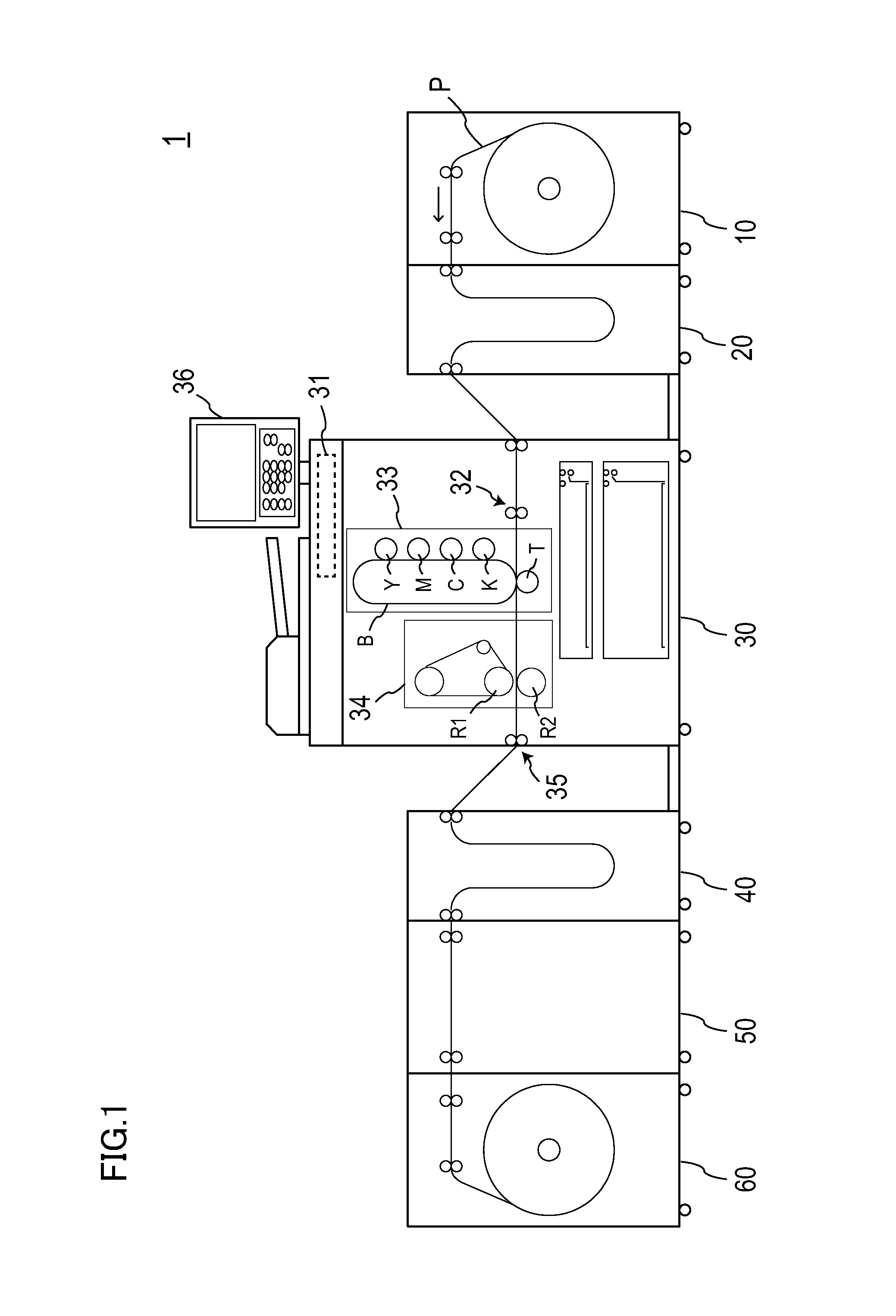
[0032]FIG. 1 is a diagram illustrating a schematic configuration example of an image forming system according to a present embodiment.

[0033]With reference to FIG. 1, a schematic configuration of an image forming system 1 will be described below.

[0034]1>

[0035]The image forming system 1 according to the present embodiment is a system where a continuous paper (including a roll paper) is used as a recording medium and an image is formed on the continuous paper.

[0036]As illustrated in FIG. 1, the image forming system 1 is configured by connecting a paper feeding apparatus 10, a pap...


PUM


Abstract

An image forming apparatus of the present invention includes: an image forming unit for forming an image on a continuous paper; a fixing unit for fixing by heat the image which has been formed on the continuous paper by the image forming unit; conveyance units for conveying the continuous paper; and a control unit for controlling the conveyance units to convey the continuous paper in such a manner that, when an image forming operation by the image forming unit is stopped, the same portion of the continuous paper, on which the image is not formed, does not remain in the fixing unit for a predetermined period of time.

Description

CROSS-REFERENCE TO RELATED APPLICATION[0001]This application is based on Japanese Patent Application No. 2013-190983 filed on Sep. 13, 2013, the contents of which are incorporated herein by reference.BACKGROUND[0002]1. Technical Field[0003]The present invention relates to an image forming apparatus, an image forming system, an image forming method, and a non-transitory computer readable recording medium stored with an image forming program.[0004]2. Description of Related Art[0005]Conventionally, there has been an image forming apparatus capable of using a continuous paper (including a roll paper) as a recording medium. In such an image forming apparatus, when the continuous paper is conveyed to a position of an image forming unit, a toner image formed in the image forming unit is transferred to the continuous paper. After that, the continuous paper is conveyed to a position of a fixing device, the toner is melted by heating, and thereby fixing the toner image on the continuous paper...

Claims


Application Information

Patent Timeline
IPC IPC(8): G03G15/00G03G15/20
CPCG03G15/2085G03G15/2078G03G15/2067G03G15/6529G03G15/2028G03G15/2032G03G15/6517G03G15/652G03G15/6526G03G2215/00455G03G2215/00603
Inventor TANIGAMI, SHINYASASAMI, SHINGOFUKAI, SHOUGOYAMANE, HIDEO
Owner KONICA MINOLTA INC
Why Eureka
Try Eureka