Apparatus for ventilating the crankcase of a combustion engine

a technology for combustion engines and apparatuses, which is applied to mechanical equipment, engine components, machines/engines, etc., can solve problems such as deteriorating the effect of apparatuses, and achieve the effects of reducing the number of line connections and other connections, and reducing the number of lines

Inactive Publication Date: 2006-04-11
HENGST WALTER
View PDF11 Cites 15 Cited by
  • Summary
  • Abstract
  • Description
  • Claims
  • Application Information

AI Technical Summary

Benefits of technology

[0005]For that reason, the present invention aims at creating an apparatus of the aforementioned type, which obviates the drawback disclosed and which, in particular, ensures that the pressure in the crankcase is reliably prevented from assuming values that are too low or too high and which, at the same time, ensures that the oil mist is, all in all, separated from the blow-by gas in a satisfactory manner.
[0006]This problem is solved by the invention by an apparatus of the aforementioned type, characterized in that a relief duct is, in addition, provided, said relief duct running from the crankcase to the intake section of the combustion engine, wherein a crankcase excess pressure limiting valve is arranged in the course of said relief duct, which valve can be adjusted dependent on the pressure such that an upper pressure limit value is prevented from being exceeded in the crankcase.
[0007]The additional relief duct and the crankcase excess pressure limiting valve provided therein are advantageous in that too high a pressure is prevented from developing in the crankcase in any operating state of the combustion engine. Once the pressure in the crankcase reaches a maximum limit value, the limiting valve and, thus, the relief duct is opened, limiting the pressure in the crankcase to this specifiable maximum pressure limit value. During operation of the combustion engine, the blow-by gas does not only flow through the relief duct, even if the limiting valve is open; a part of the blow-by gas also flows through the ventilation duct and the oil-mist separator provided therein. If the pressure in the crankcase is below the upper pressure limit value, the limiting valve is closed and blow-by gas does not flow through the relief duct. In this case, the total amount of blow-by gas flows through the ventilation duct and the oil-mist separator provided therein. Hence, the relief duct is opened only in operating states of the combustion engine that occur relatively rarely. The relief duct is closed by the excess pressure limiting valve for most of the operating time. In order to achieve quick and efficient relief from pressure in the crankcase if need be, components with an excessively high flow resistance which might cause development of a differential pressure are not provided in the relief duct. If necessary, it may be appropriate to incorporate an additional coarse-particle separator with low resistance in the relief duct, in order to also avoid oil from being entrained over to the pure or oil free side when the relief duct is open. Hence, it must also be assumed that the oil mist contained in the blow-by gas flowing through the relief duct is not completely separated therefrom. This appears to be to disadvantage at first sight, but does, in practice, not deteriorate the effect of the apparatus as such.

Problems solved by technology

This appears to be to disadvantage at first sight, but does, in practice, not deteriorate the effect of the apparatus as such.

Method used


Image

  • Apparatus for ventilating the crankcase of a combustion engine
  • Apparatus for ventilating the crankcase of a combustion engine
  • Apparatus for ventilating the crankcase of a combustion engine

Examples


Embodiment Construction

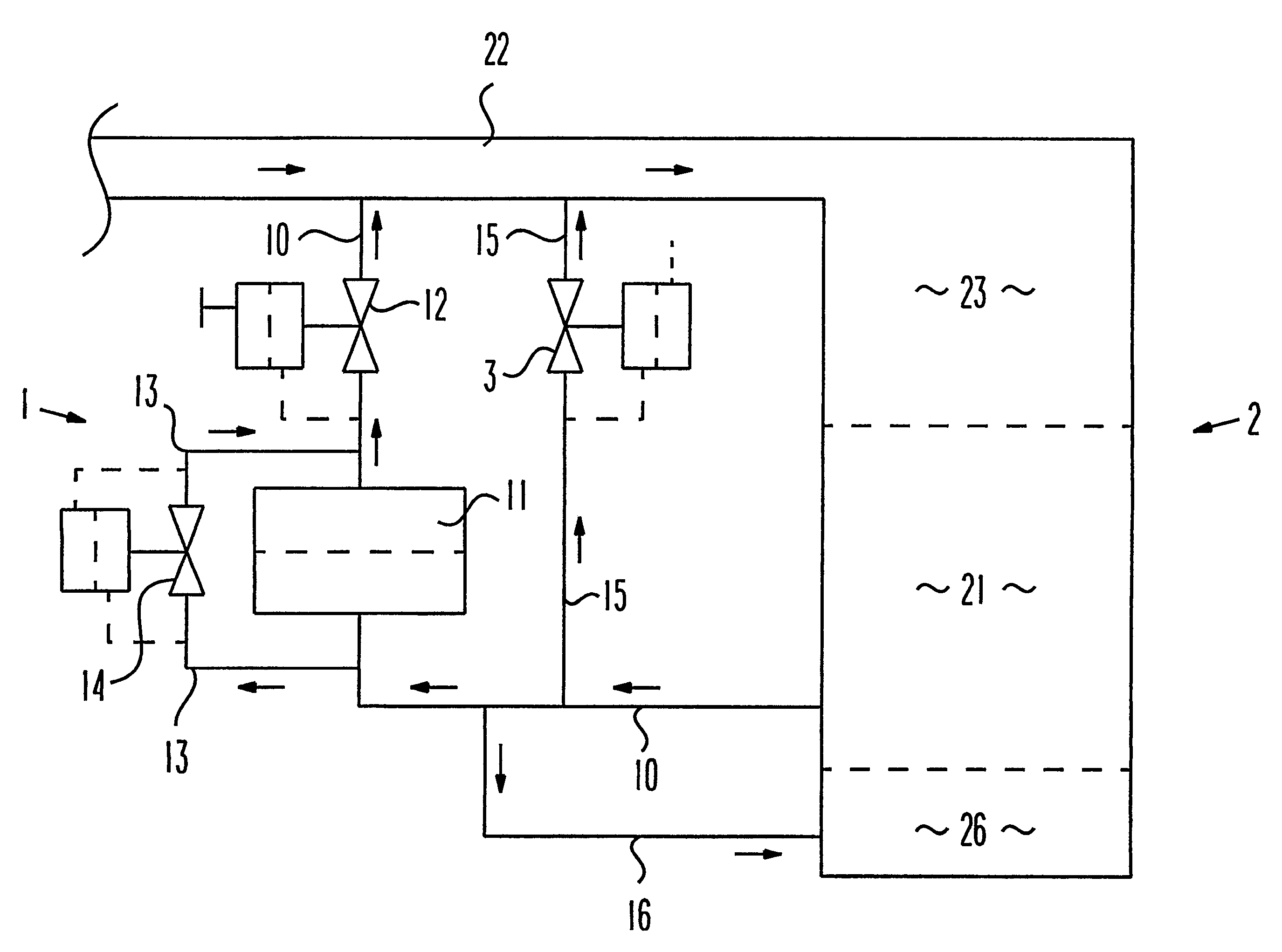
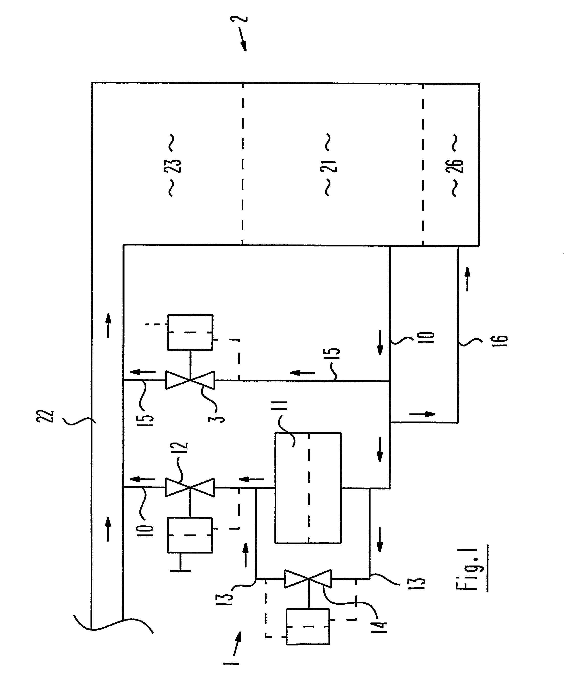
[0023]To its extreme right, FIG. 1 of the drawing shows a combustion engine 2 that comprises a crankcase 21 in its lower part and one or more combustion chambers 23 in its upper part. An intake section 22 through which combustion air is supplied to the combustion chambers 23 of the combustion engine 2 ends in the combustion chambers 23.

[0024]An apparatus 1 for ventilating the crankcase 21 is allocated to the combustion engine 2. This apparatus 1 first comprises a ventilation duct 10 that starts in the crankcase 21 and extends to the intake section 22. An oil-mist separator 11 used to separate oil mist consisting of fine oil droplets from blow-by gas that is supplied from the crankcase 21 into the intake section 22 is arranged in the course of this ventilation duct 10. Furthermore, a crankcase vacuum pressure regulating valve 12 is provided in the ventilation duct 10, downstream of the oil-mist separator 11 as seen in flow direction. This regulating valve 12 serves to limit the vacuu...


PUM


Abstract

The invention relates to a device for crankcase ventilation of an internal combustion engine, comprising a ventilation duct extending from the crankcase to an induction tract of the internal combustion engine, whereby at least one oil vapor separator causing a drop in pressure is arranged in said duct and a crankcase vacuum control valve is arranged upstream or downstream therefrom and can be adjusted according to the pressure in the crankcase such that a lower pressure threshold valve in the crankcase is respected. The novel device is characterized in that a discharge duct extending from the crankcase to the induction tract of the internal combustion engine is also provided, whereby a crankcase overpressure limiting valve is disposed inside said duct and can be adjusted in a pressure-dependent manner to ensure that an upper pressure threshold in the crankcase is not exceeded.

Description

BACKGROUND OF THE INVENTION[0001]The present invention relates to an apparatus for ventilating the crankcase of a combustion engine, comprising a ventilation duct running from the crankcase to an intake section of the combustion engine and at least one oil-mist separator that causes a pressure drop and is arranged in the course of the ventilation duct, with a crankcase vacuum pressure regulating valve that is installed upstream or downstream of the oil-mist separator and is adjustable dependent on the crankcase pressure such that the pressure in the crankcase is prevented from falling below a lower pressure limit value.[0002]During operation of a combustion engine, gas is pressed out of the combustion chamber and into the crankcase through the gap between the piston rings and the cylinder walls, this gas being called blow-by gas. This gas increases the pressure in the crankcase and must, therefore, be removed. Usually, the blow-by gas is supplied into the intake section of the combu...

Claims


Application Information

Patent Timeline
Patent Type & Authority Patents(United States)
IPC IPC(8): F01M13/02F01M13/00
CPCF01M13/022F01M2013/0055
Inventor PIETSCHNER, SIEGHARD
Owner HENGST WALTER
Why Eureka
Try Eureka