Slew drive gearbox and clamp

a gearbox and clamping technology, applied in the direction of rod connection, lighting and heating apparatus, gearing, etc., can solve the problems of increasing cost and time and effort, and achieve the effect of reducing installation time, cost and weight, and simplifying installation

Active Publication Date: 2015-03-26
KINEMATICS LLC
View PDF6 Cites 30 Cited by
  • Summary
  • Abstract
  • Description
  • Claims
  • Application Information

AI Technical Summary

Benefits of technology

[0008]A further object of the [present invention is to provide a slew drive with a clamp fo

Problems solved by technology

Each of these requires time

Method used


Image

  • Slew drive gearbox and clamp
  • Slew drive gearbox and clamp
  • Slew drive gearbox and clamp

Examples


Embodiment Construction

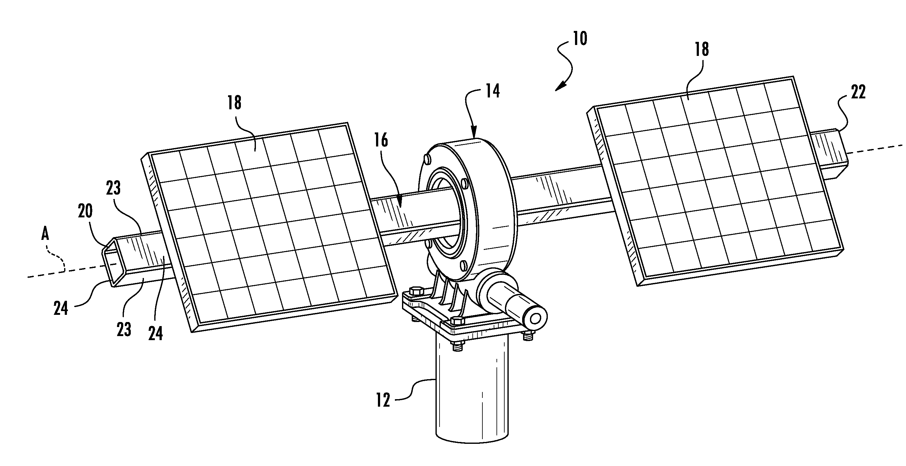
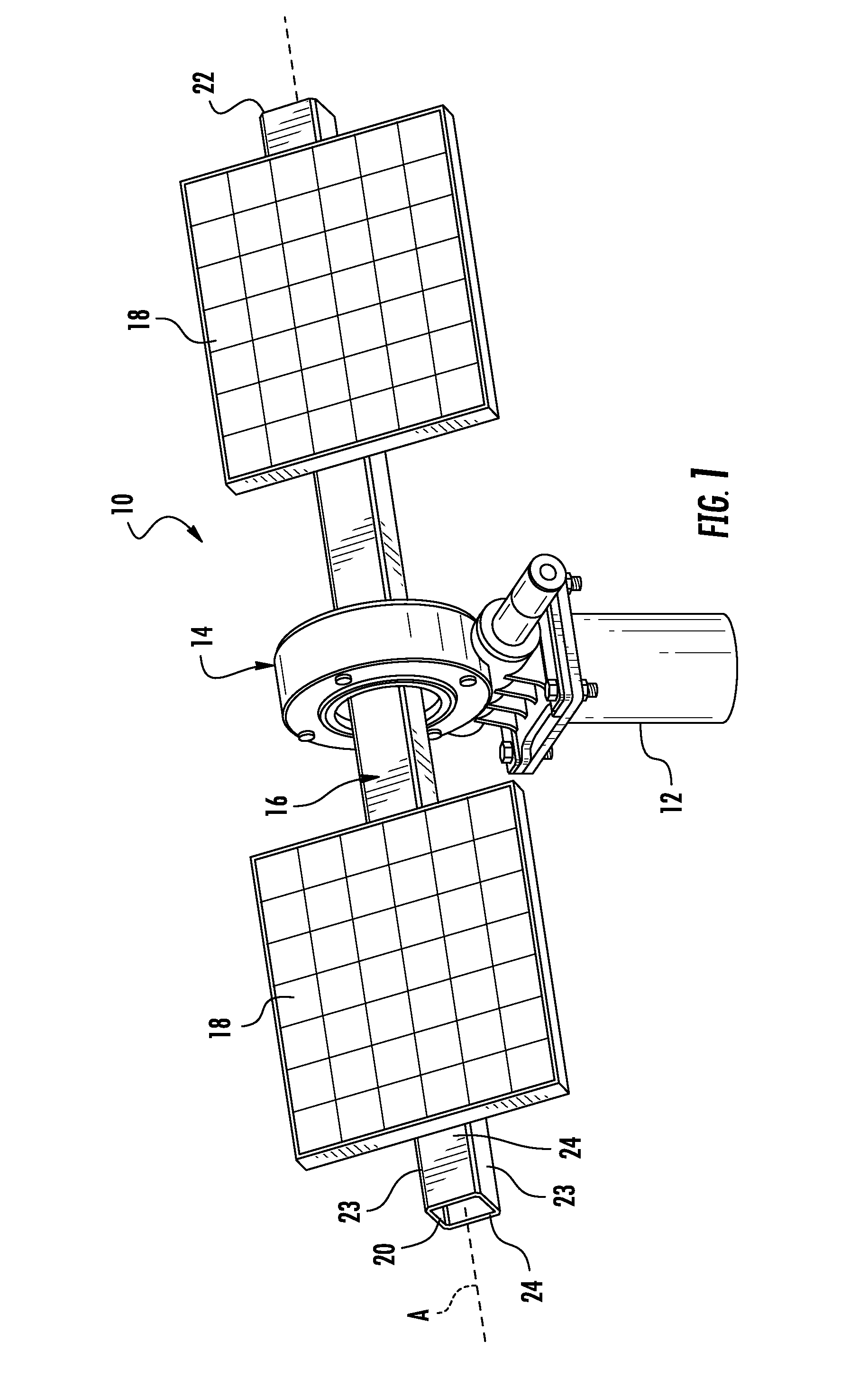
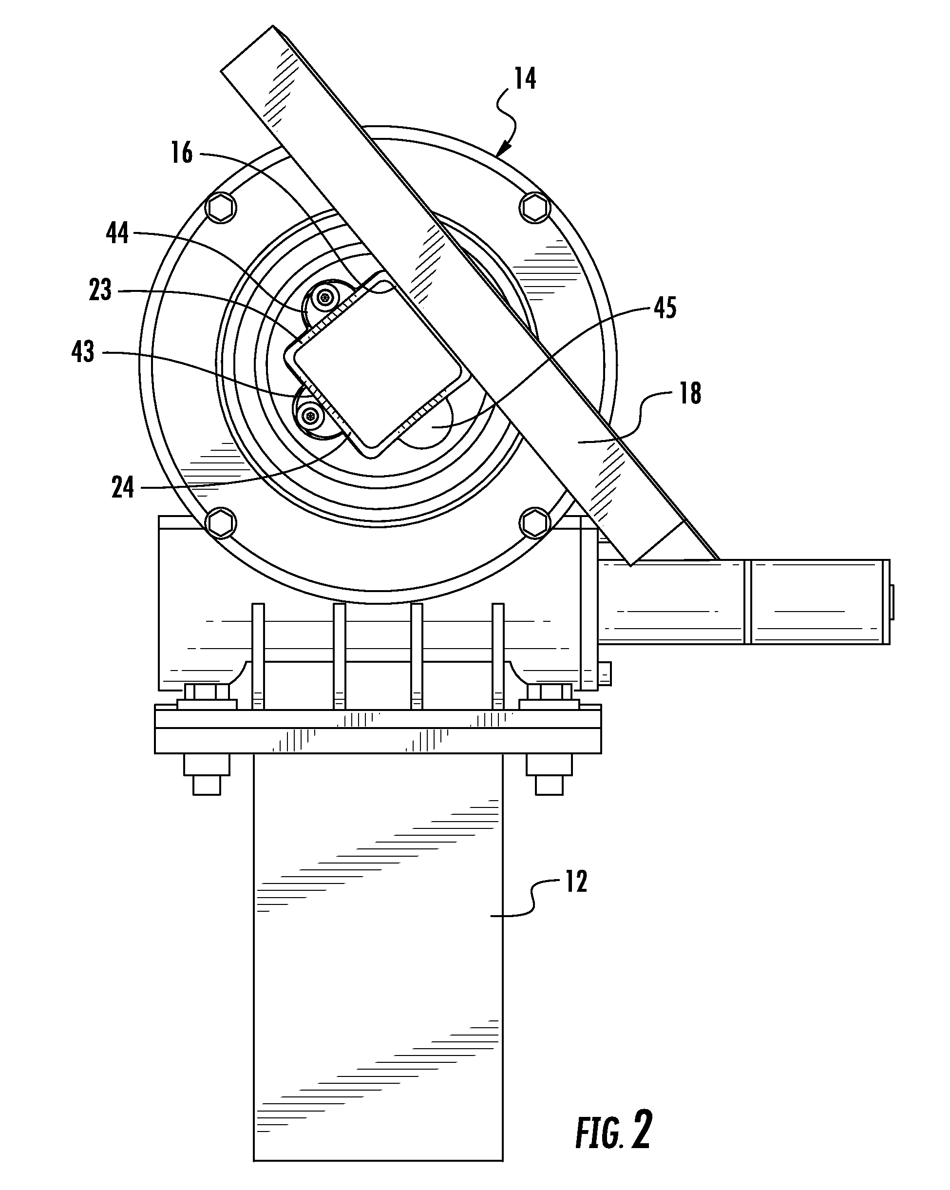
[0026]Turning now to the drawings in which like reference characters indicate corresponding elements throughout the several views, attention is directed to FIGS. 1 and 2 which illustrate a solar panel assembly generally designated 10. Assembly 10 includes a support post 12, a slew drive 14 carried by post 12, a transverse support member 16 extending through and rotated by slew drive 14, and solar panels 18 carried by transverse support member 16. Transverse support member 16 includes an end 20, and an opposing end 22 extending along a longitudinal axis A. In the preferred embodiment, transverse support member 16 is an elongated metal tube having a square cross section with opposed surfaces 23 extending from end 20 to opposing end 22 and opposed surface 24 extending from end 20 to opposing end 22. It will be understood that while transverse support member 16 is preferably tubular and metallic, it can also be a solid member, and can be made of wood, plastic and the like. Additionally,...


PUM


Abstract

A slew drive with clamp including a slew drive having a housing, a worm shaft having a worm thread carried within the housing for rotational movement, a torque tube having an outer diameter and a central socket extending therethrough, the torque tube carried by the housing for rotational movement perpendicularly to the worm shaft and worm thread, and coupling means for rotatably engaging the torque tube with the worm threads. A transverse support member is received in the socket and extends substantially perpendicularly therefrom. A clamp is carried within the socket movable between a clamped and an unclamped position for clamping the transverse member fixedly within the socket.

Description

CROSS-REFERENCE TO RELATED APPLICATION[0001]This application claims the benefit of U.S. Provisional Application No. 61 / 880,101, filed 19 Sep. 2013 and U.S. Provisional Application No. 61 / 884,389, filed 30 Sep. 2013.FIELD OF THE INVENTION[0002]This invention relates to solar panel support frameworks.[0003]More particularly, the present invention relates to Slew drive gearboxes.BACKGROUND OF THE INVENTION[0004]In the field of drive systems, and in particularly slewing drives, the ability to attach a transverse support member is unknown. Previous drives have required specialized coupling members or brackets to enable attachment of structures thereto. These structures have also require modification to couple to the specialized coupling members. Each of these requires time and effort, increasing cost.[0005]It would be highly advantageous, therefore, to remedy the foregoing and other deficiencies inherent in the prior art.[0006]An object of the present invention is to provide a new and im...

Claims


Application Information

Patent Timeline
IPC IPC(8): F16H19/02
CPCF16H19/02F16B2/14F16B7/0493F16H19/08F16H57/039F24S30/425F24S2025/6003F24S2030/134H02S20/32Y02E10/47Y02E10/50Y10T74/18792
Inventor MORGAN, BRENT
Owner KINEMATICS LLC
Why Eureka
Try Eureka