Parallel aspirator arrangement for vacuum generation and compressor bypass

a vacuum generation and compressor technology, applied in the direction of combustion engines, combustion air/fuel air treatment, combustion feed systems, etc., can solve the problems of compressor degradation, affecting the operation of compressors, and incorporating such valves, so as to prevent objectionable audible noise, significant component and operating costs, and extend the operating region of engines

Inactive Publication Date: 2015-03-26
FORD GLOBAL TECH LLC
View PDF2 Cites 40 Cited by
  • Summary
  • Abstract
  • Description
  • Claims
  • Application Information

AI Technical Summary

Benefits of technology

[0002]Turbocharging an engine allows the engine to provide power similar to that of a larger displacement engine. Thus, turbocharging can extend the operating region of an engine. Turbochargers function by compressing intake air in a compressor via a turbine operated by exhaust gas flow. Under certain conditions, the flow rate and pressure ratio across the compressor can fluctuate to levels that may result in noise disturbances, and in more severe cases, performance issues and compressor degradation. Such compressor surge may be mitigated by one or more compressor bypass valves (CBVs). The CBVs may recirculate compressed air from the compressor outlet to the compressor inlet, and thus may be arranged in a passage which is coupled to the intake upstream of the compressor and downstream of the compressor in some examples. In some examples, continuous CBVs (CCBVs) may be used, which provide a continuous and continually variable circulation flow from downstream of the compressor to upstream of the compressor. CCBVs may provide boost control and compressor surge avoidance, and may further prevent objectionable audible noise. However, incorporation of such valves can add significant component and operating costs to engine systems.
[0005]Many additional advantages may be achieved by the embodiments described herein. For example, because multiple, parallel aspirators are used, each aspirator may have a relatively small flow diameter and yet the arrangement can still achieve an overall motive flow rate commensurate with that of a single larger aspirator when needed. The relatively small flow diameters of the aspirators enable the use of smaller, cheaper valves controlling their motive flow. Further, relative flow diameters of the parallel aspirators may be strategically selected such that the valves of the aspirators may be controlled to achieve a desired set of discrete levels of motive flow through the arrangement. Furthermore, because the combined motive flow rate through the aspirator arrangement is controllable via the valves, conditions where the motive flow through the aspirators may cause air flow greater than desired may be reduced. Thus, since air flow rate greater than desired can lead to extra fuel being injected, fuel economy may be improved by use of the aspirator arrangement.

Problems solved by technology

Under certain conditions, the flow rate and pressure ratio across the compressor can fluctuate to levels that may result in noise disturbances, and in more severe cases, performance issues and compressor degradation.
However, incorporation of such valves can add significant component and operating costs to engine systems.
Whereas conventional vacuum pumps produce a pumping curve which is independent of intake manifold pressure, pumping curves for aspirators arranged in engine intake systems may be unable to consistently provide a desired performance over a range of intake manifold pressures.
Further, if an aspirator is large enough to replace a conventional vacuum pump, it may flow too much air into the intake manifold for economical fuel use.
However, again, adding valves to engine systems can add significant component and operating costs.

Method used


Image

  • Parallel aspirator arrangement for vacuum generation and compressor bypass
  • Parallel aspirator arrangement for vacuum generation and compressor bypass
  • Parallel aspirator arrangement for vacuum generation and compressor bypass

Examples


Embodiment Construction

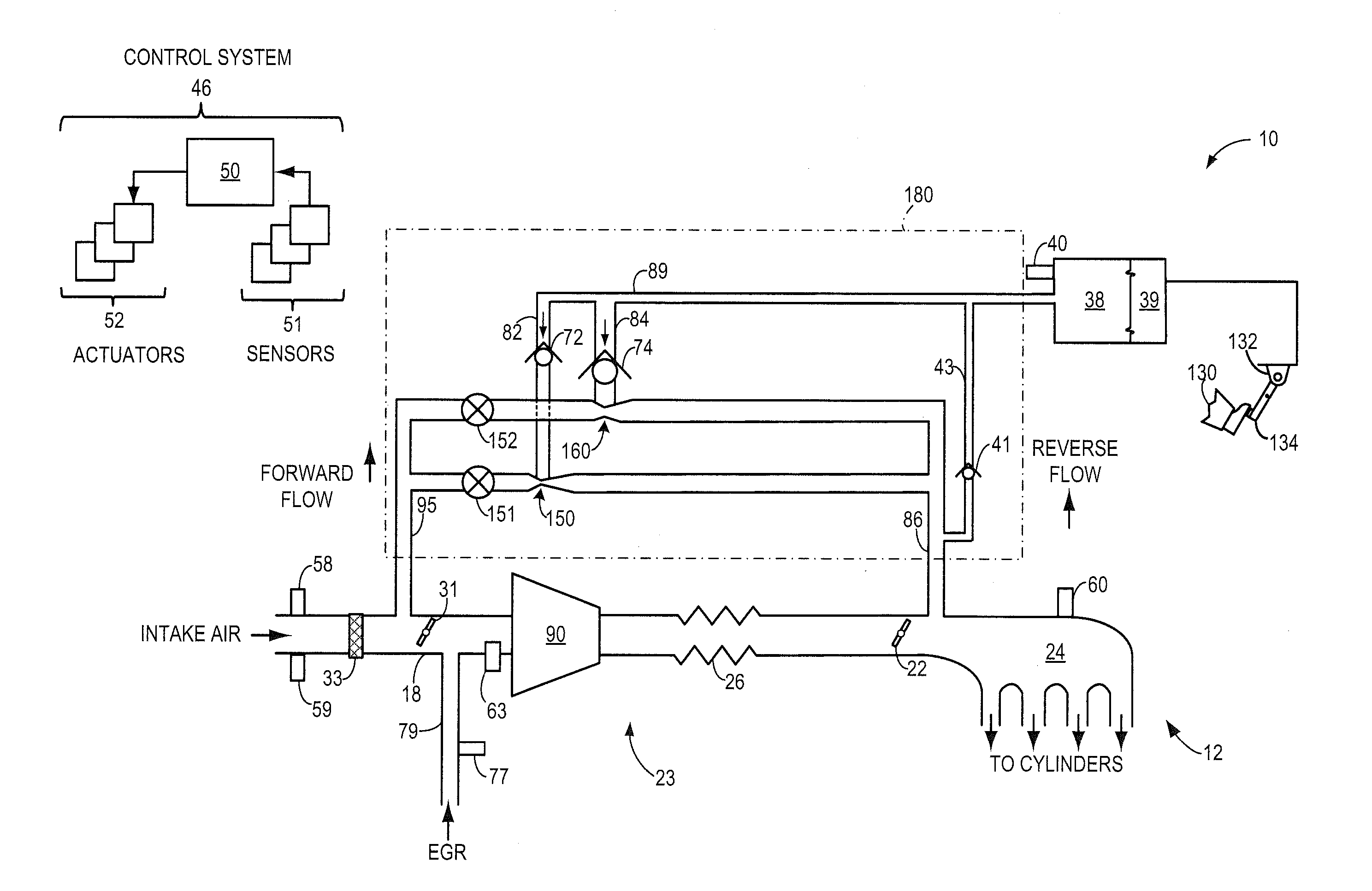
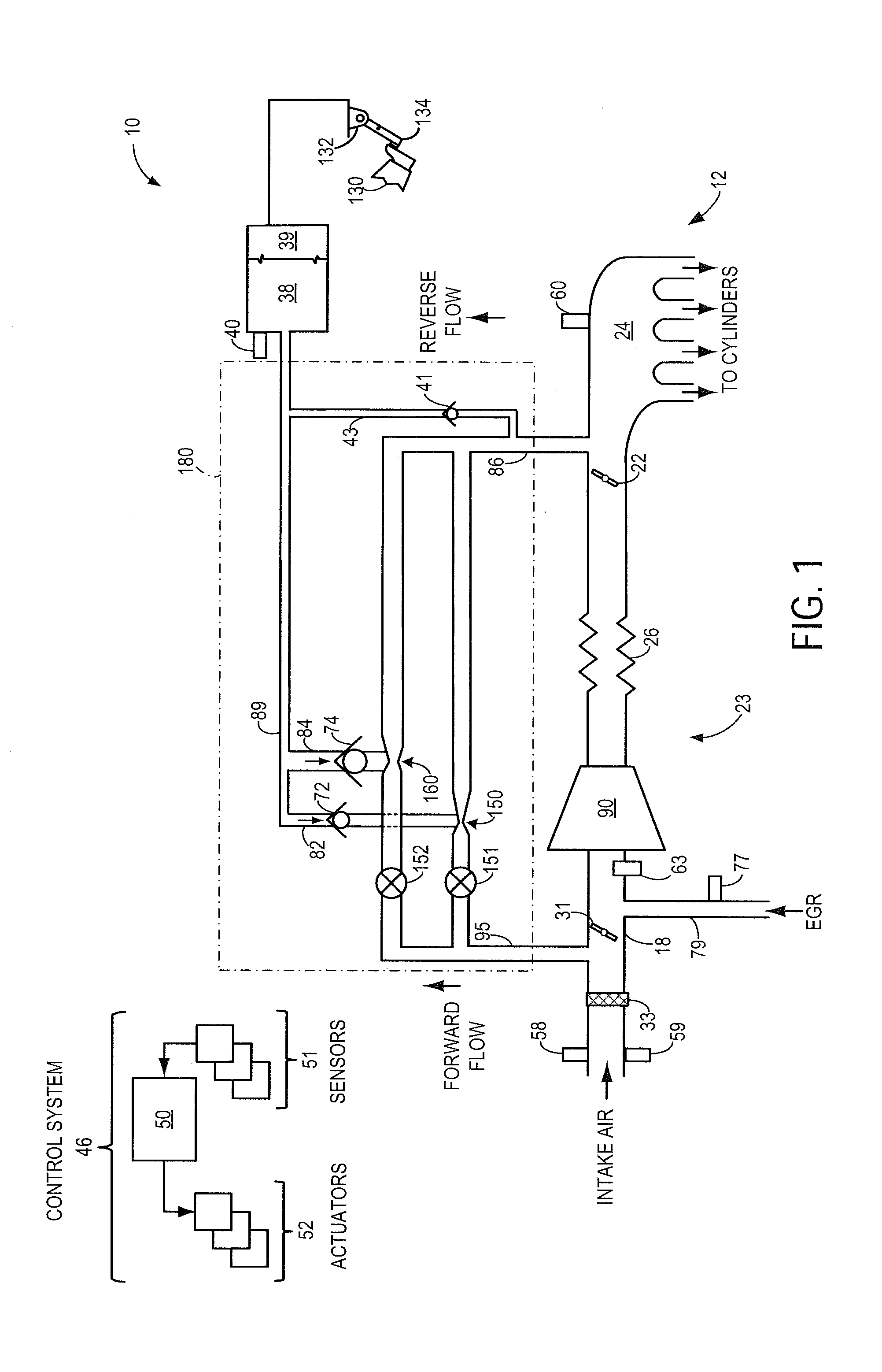
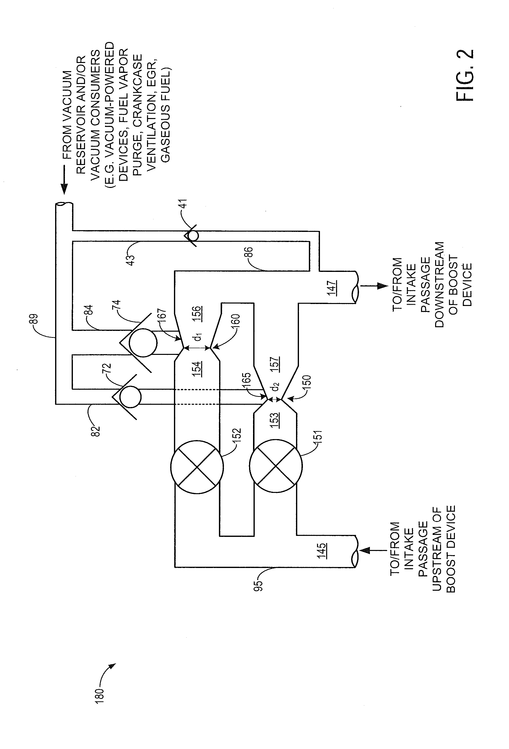
[0019]Methods and systems are provided for controlling a motive flow rate through a parallel arrangement of valved aspirators bypassing a boost device arranged in an intake of an engine system such as the engine systems depicted in FIGS. 1 and 3. A detail view of an exemplary aspirator arrangement which may be included in the engine system of FIG. 1 is provided in FIG. 2, a detail view of an exemplary aspirator arrangement which may be included in the engine system of FIG. 3 is provided in FIG. 4, and a detail view of an exemplary aspirator arrangement which may be included in either of the engine systems of FIGS. 1 and 3 is provided in FIG. 5. A graph depicting ideal engine air flow rate versus engine air flow rate achievable when flow is directed through an aspirator arrangement such as the aspirator arrangement shown in FIG. 2, during non-boost conditions, is provided in FIG. 6A. As noted above, a rate of level of flow through an aspirator arrangement may be varied, e.g. to one o...


PUM


Abstract

Methods and systems are provided for a parallel arrangement of at least two aspirators bypassing an intake compressor in an engine system, the aspirator arrangement including an aspirator shut-off valve arranged in series with each aspirator. The aspirator shut-off valves may be controlled based on engine vacuum needs as well as based on intake manifold pressure, during non-boost conditions, and compressor surge, during boost conditions. For example, during boost conditions, the aspirator shut-off valves may be controlled to enable a selectable discrete compressor recirculation flow rate, whereas during non-boost conditions the aspirator shut-off valves may be controlled to enable a selectable, discrete level of vacuum generation for use by various engine vacuum consumers.

Description

FIELD[0001]The present application relates to parallel arrangements of valved aspirators coupled to an engine system. In one example, a combined motive flow rate through the aspirators may be controlled to provide discrete levels of vacuum generation during non-boost conditions, and to provide discrete levels of continuous compressor bypass flow during boost conditions.BACKGROUND AND SUMMARY[0002]Turbocharging an engine allows the engine to provide power similar to that of a larger displacement engine. Thus, turbocharging can extend the operating region of an engine. Turbochargers function by compressing intake air in a compressor via a turbine operated by exhaust gas flow. Under certain conditions, the flow rate and pressure ratio across the compressor can fluctuate to levels that may result in noise disturbances, and in more severe cases, performance issues and compressor degradation. Such compressor surge may be mitigated by one or more compressor bypass valves (CBVs). The CBVs m...

Claims


Application Information

Patent Timeline
Patent Type & Authority Applications(United States)
IPC IPC(8): F02D23/00F02D33/02
CPCF02D33/02F02D23/00F02B37/16F02M35/10229F02B37/162Y02T10/12
Inventor PURSIFULL, ROSS DYKSTRA
Owner FORD GLOBAL TECH LLC
Why Eureka
Try Eureka