Apparatus for retarding rotary nozzle speed

a technology of rotary nozzle and retarder, which is applied in the direction of movable spraying apparatus, liquid resistance brakes, brake types, etc., can solve the problem of torque range limitation, and achieve the effect of increasing the torque range of the tool

Active Publication Date: 2015-03-26
STONEAGE
View PDF10 Cites 11 Cited by
  • Summary
  • Abstract
  • Description
  • Claims
  • Application Information

AI Technical Summary

Benefits of technology

[0005]The present disclosure directly addresses such needs. The present disclosure addresses this limited torque range by offering a solution that involves permitting the distance of the gap between relatively rotating components connected to a rotary nozzle tool to vary as a function of tool torque, affecting the rotational speed to the tool, thus increasing the operational torque range of the tool.
[0007]In one preferred embodiment, the rotary shaft and the hollow housing have complementary frusto-conical shapes. As speed increases, the cams of the cam assembly rotate and separate, causing the shaft to move forward, reducing the gap between the shaft and the hollow housing, increasing the resistive drag force of the fluid on the rotating shaft, thus slowing it down until an equilibrium is again reached between spring force and the viscous drag force on the rotor. Conversely, as speed decreases, the spring forces push the shaft rearward, closing the cams and increasing the viscous fluid volume in the gap thus decreasing viscous drag until equilibrium is again reestablished. The combination of these changes substantially increases the useable range of torques that can be handled by the speed retarding apparatus.

Problems solved by technology

This limit in torque range requires that other components on the rotary nozzle be changed to accommodate major variations in flow and pressure.

Method used


Image

  • Apparatus for retarding rotary nozzle speed
  • Apparatus for retarding rotary nozzle speed
  • Apparatus for retarding rotary nozzle speed

Examples


Embodiment Construction

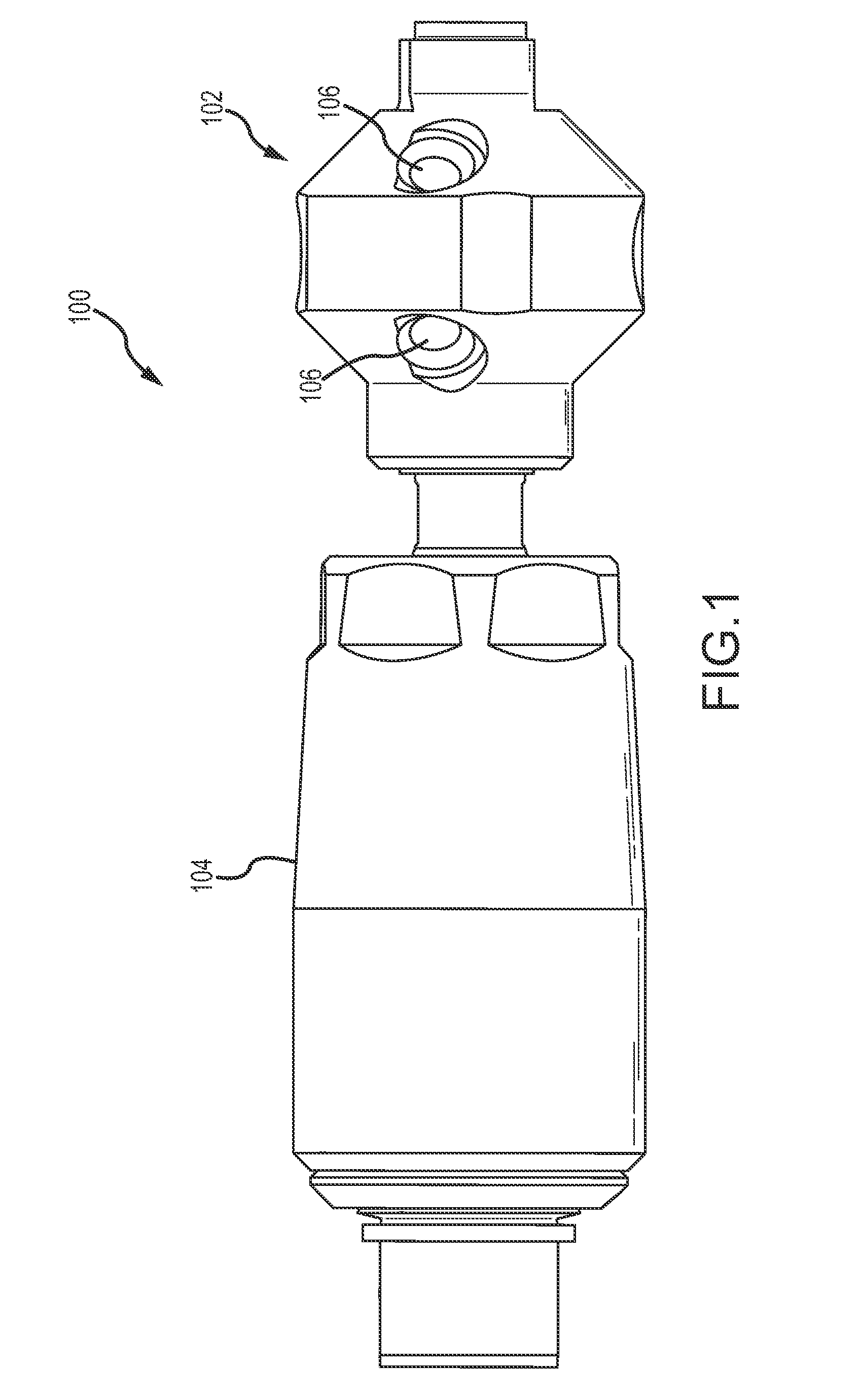
[0021]An assembled exemplary embodiment of a speed controlled rotary nozzle assembly 100 in accordance with the present disclosure is shown in a longitudinal side view in FIG. 1. The assembly 100 includes a rotary nozzle head 102 fastened to a speed limiting apparatus or device 104 in accordance with the present disclosure. The rotary nozzle head 102 preferably has a plurality of radially offset nozzle ports 106 for generating a rotational torque about the longitudinal axis A of the assembly 100 when high pressure fluid is pumped through the assembly 100 and ejected out of the nozzle ports 106.

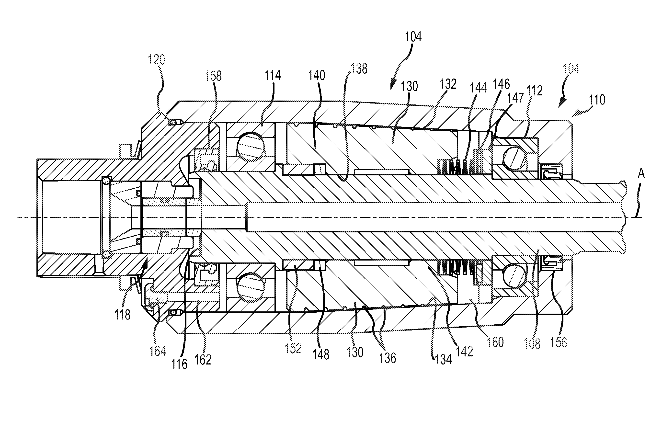
[0022]The speed limiting device 104 includes a tubular shaft 108 rotatably supported within a hollow housing 110. One end of the tubular shaft 108 extends from one end of the housing 110 and is supported by a roller journal bearing 112 in the housing 110. The rear end of the tubular shaft 108 is rotatably supported in the housing 110 by a rear roller bearing 114 mounted within the housing 110....


PUM


Abstract

An apparatus for retarding rotation of a nozzle includes a hollow housing, a rotary shaft within the housing, a rotatable rotor on the rotary shaft free to move axially along the shaft, and a cam assembly coupling the rotor and shaft together in the housing such that rotor rotation on the shaft causes the cam assembly to displace the rotor axially on the shaft in a first direction. A set of springs on the shaft biases the rotor in a second direction opposite the first direction on the shaft. Finally, a viscous fluid disposed between the rotor and the housing generates a drag on rotor rotation with the shaft. Relative rotation of the rotor with respect to the shaft in conjunction with a variable gap between the rotor and housing are used to slow and thus control rotary nozzle speed.

Description

CROSS REFERENCE TO RELATED APPLICATIONS[0001]This application claims the benefit of priority of U.S. Provisional Patent Application Ser. No. 61 / 880,316, filed Sep. 20, 2013, the disclosure of which is incorporated herein by reference in its entirety.BACKGROUND OF THE DISCLOSURE[0002]The present disclosure is directed to high pressure fluid rotary nozzle systems. In particular, embodiments of the present disclosure are directed to an apparatus for retarding the rotational speed of such rotary nozzles.[0003]A high pressure rotary nozzle and tractor device is disclosed in US Patent Application Publications 2012 / 0204368 and 2012 / 0205405. Such nozzles and tractor devices are particularly well suited to industrial uses where the operating parameters can be in the range of 1,000 to 40,000 psi, rotating speeds of up to 1000 rpm or more and flow rates of 2 to 50 gpm may be needed.[0004]In order to control the rotational speed of the rotary nozzle and tractor devices, there is a need for a sp...

Claims


Application Information

Patent Timeline
Patent Type & Authority Applications(United States)
IPC IPC(8): B05B3/00F16D57/00
CPCF16D57/007B05B3/005B05B3/06
Inventor ANDERSEN, COLTON
Owner STONEAGE
Why Eureka
Try Eureka