

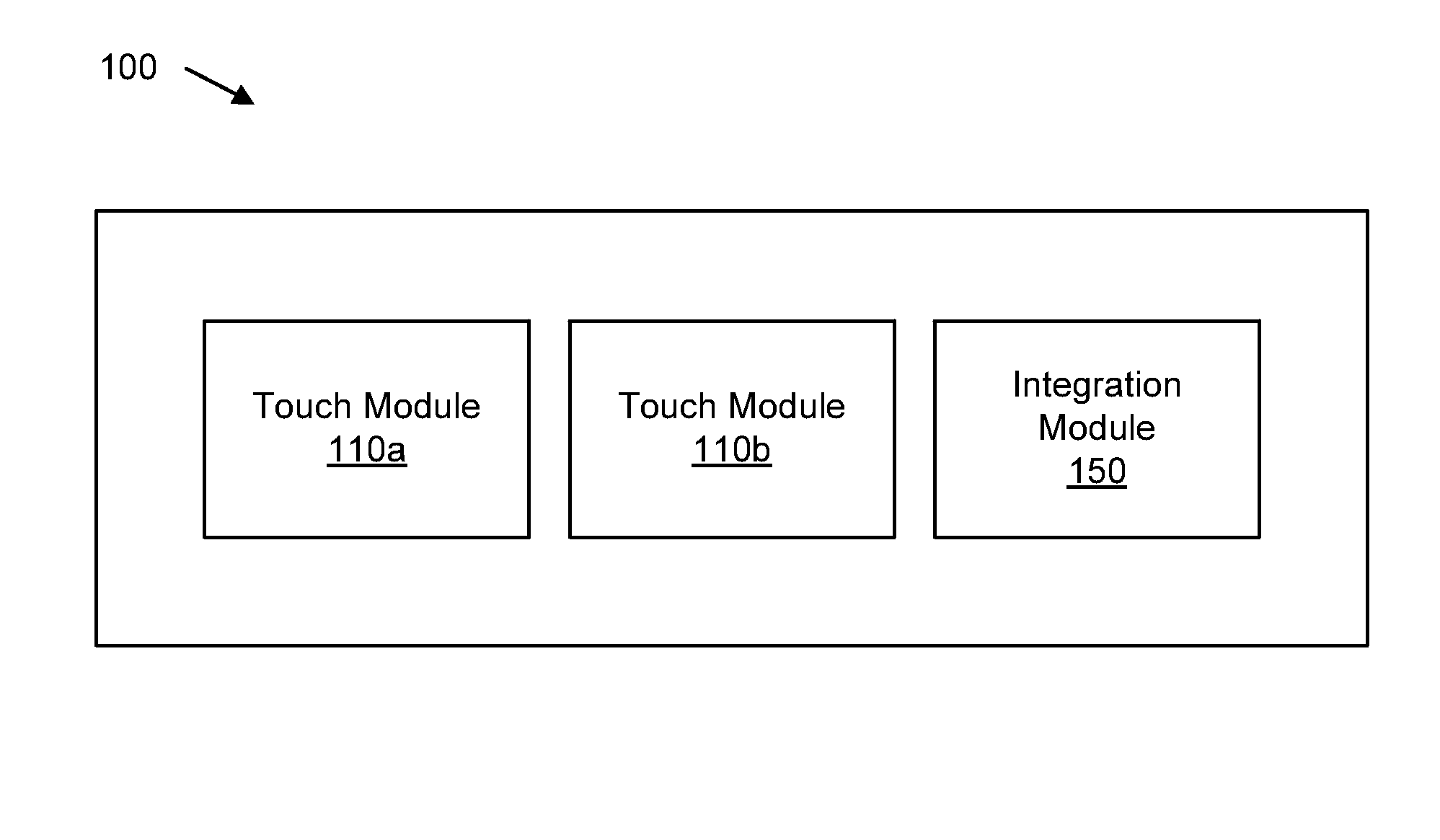
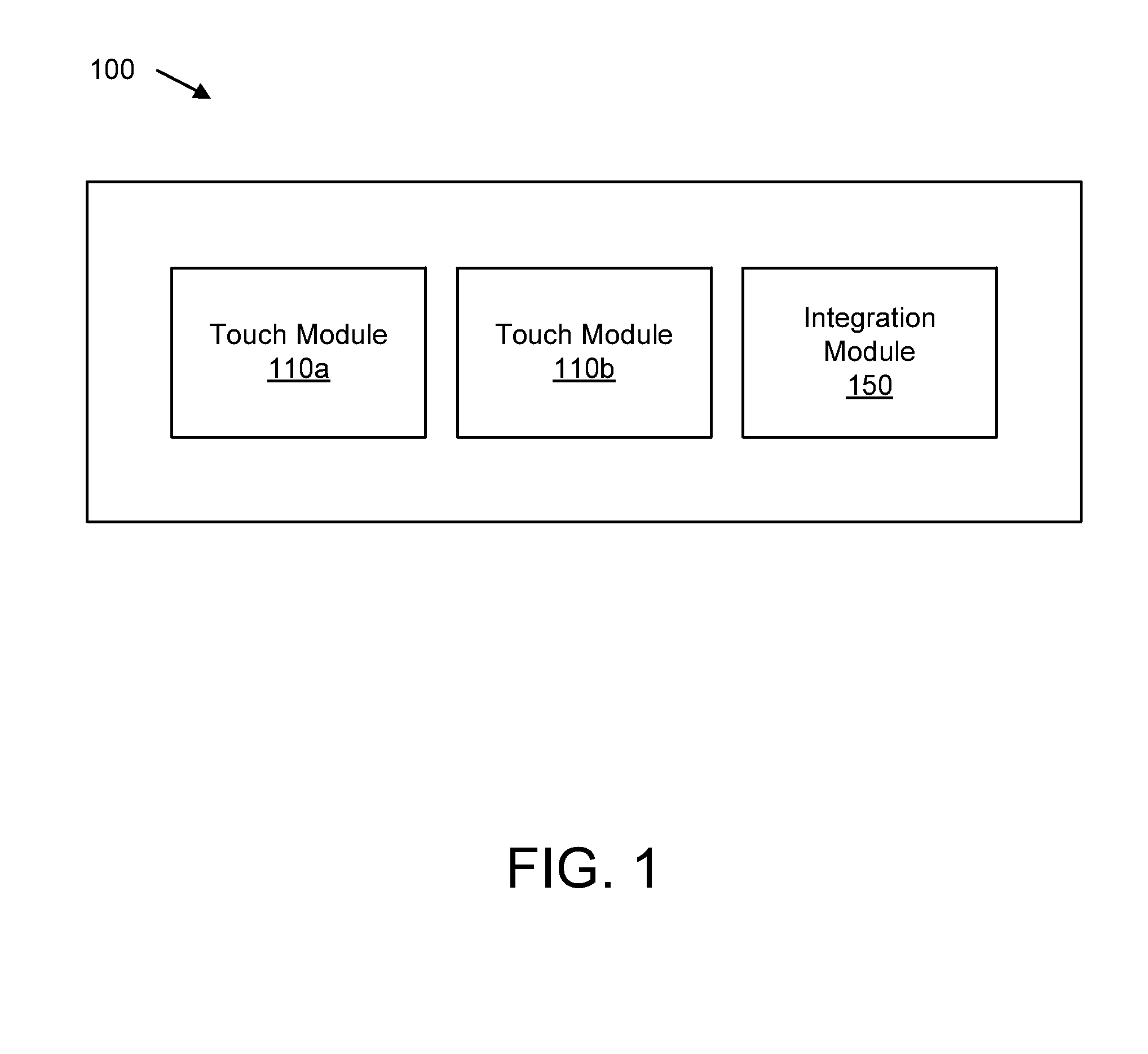
Integrating multiple different touch based inputs
a touch input and input technology, applied in the field of touch interfaces, can solve the problems of computing devices to behave unexpectedly, users may inadvertently touch the screen with a wrist or palm,
- Summary
- Abstract
- Description
- Claims
- Application Information
AI Technical Summary
Benefits of technology
Problems solved by technology
Method used
Image

Examples
embodiment 400
[0070]FIG. 4 is an illustration illustrating one embodiment 400 of multiple touches on a touch screen. As previously described, a touch sensor may detect a touch at a screen. For example, a touch 420 may be detected by any of the previously described touch sensors. Over time, as previously described, many touches may resemble touch pattern 430. In one embodiment, a touch sensor may determine that the touch 430 may not be an intended touch by a user. In one example, the touch 430 may be a result of a palm rest, or wrist touch (e.g. not a finger or other pointing device). In another embodiment, touch 410 may be a result from a detected touch by a magnetic resonance touch sensor, while touch 420 may be detected by a capacitive touch sensor. Therefore, in one embodiment, a touch module 110a may detect a touch 430, and a touch module 110b may detect a touch 410. An integration module may concurrently process input from touch 430 and 410.
[0071]In one embodiment, a capacitive touch sensor ...
embodiment 500
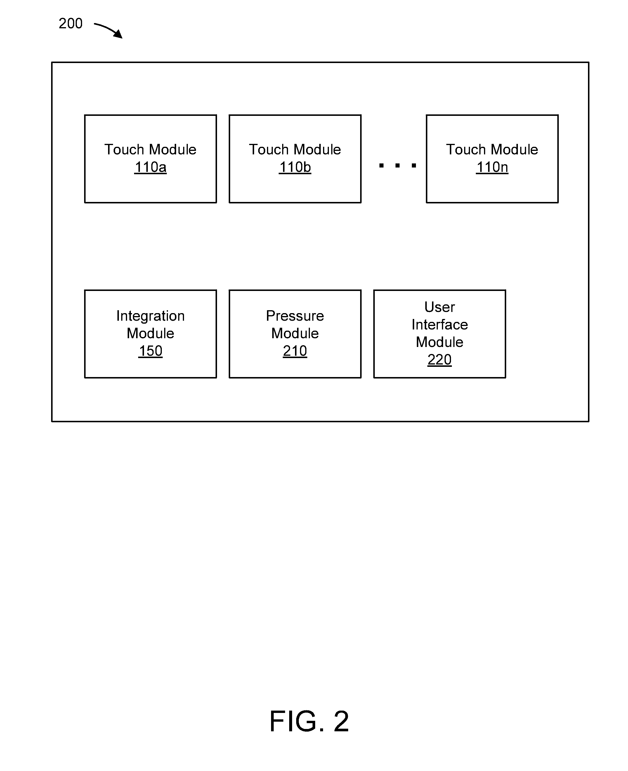
[0073]FIG. 5 is an illustration depicting one embodiment 500 of a computing device with a screen for a screen implementing multiple touch based inputs. In one embodiment, the computing device may include a screen 560, a capacitive touch module 110a and a magnetic resonance touch module 110b. Initially, a capacitive touch module 110a may be disabled. A user may be in the process of drawing a line with a magnetic pen 520 via a magnetic resonance touch module 110b. The line may begin with line 510 and continue to line 512 (not yet completed). While a user is in the process of drawing a line 510,512 a notification 530 may be received by the user interface module 220.
[0074]In another embodiment, when a notification is received, a user interface module 220 may display the notification 530 to the user. A user may acknowledge the notification by pressing on the notification 530. Prior to the user pressing on the notification 530, the capacitive touch module may be disabled. In response to a...
embodiment 600
[0076]FIG. 6 is another illustration depicting one embodiment 600 of a user interface for a computing device implementing multiple different touch based inputs. In one embodiment, a computing device may include a screen 630, a capacitive touch module 110a and a magnetic resonance touch module 110b. Initially, a capacitive touch module 110a may be disabled. A user may be in the process of drawing a line with a magnetic pen 620 via a magnetic resonance touch module 110b. The line may begin with line 610 and continue to line 612 (not yet completed). While a user is in the process of drawing a line 610,612 a user may desire to zoom in a current view.
[0077]In one embodiment, a user may begin a zooming action by pressing two fingers 640 on the screen 630 at location 660. Prior to beginning the zooming action, the capacitive touch module 110a may be disabled. In response to a pressure from the user pressing on the screen 630 at location 660 exceeding a pressure threshold value, the integra...
PUM
 Abstract
Description
Claims
Application Information