Automated relief valve control system and method

a control system and relief valve technology, applied in the field of valve control system and method, can solve the problems of less accurate popoff pressure limit and increased wear of the relief valve, and achieve the effect of increasing the pressure of the pressurized gas

Active Publication Date: 2014-02-20
SPM OIL & GAS INC
View PDF1 Cites 44 Cited by
  • Summary
  • Abstract
  • Description
  • Claims
  • Application Information

AI Technical Summary

Benefits of technology

[0031]In a third aspect, there is provided a method of controlling a pressure relief valve in a downhole operation, the method including maintaining a pressure relief valve in a closed state with a pressurized gas from a gas source; detecting, with a pressure sensor disposed adjacent the pressure relief valve, a fluid pressure in a high pressure tube extending between a pump and a wellhead; comparing the fluid pressure in the high pressure tube to a stored fluid pressure threshold; sending a signal to open a dump valve if the fluid pressure in the high pressure tube exceeds the fluid pressure threshold; and opening the dump valve to lower the pressure of the pressurized gas until the pressure relief valve changes from the closed state to the open state.
[0032]In an exemplary embodiment, the method includes prompting an operator to enter the fluid pressure threshold; prompting an operator to enter a reset pressure threshold; and closing the dump valve to increase the pressure of the pressurized gas when the fluid pressure in the high pressure tube is below the reset pressure threshold.
[0033]In another exemplary embodiment, the method includes regulating the pressure of the pressurized gas that maintains the pressure relief valve in a closed state with a reducing valve; and controlling the reducing valve with an electronic controller in response to the fluid pressure threshold.
[0034]In yet another exemplary embodiment, regulating the pressure of the pressurized gas includes maintaining the pressurized gas at a pressure about 105-150% of a gas pressure threshold that opens the relief valve.
[0035]In certain exemplary embodiments, the method includes changing the pressure of the pressurized gas with the reducing valve in response to changes in the fluid pressure threshold.

Problems solved by technology

However, the relief valve has traditionally been difficult to calibrate in the field and is subject to wear as pressure fluctuations occur, resulting in valve chatter, increased wear, and ultimately a less than accurate popoff pressure limit on the relief valve.

Method used


Image

  • Automated relief valve control system and method
  • Automated relief valve control system and method
  • Automated relief valve control system and method

Examples


Embodiment Construction

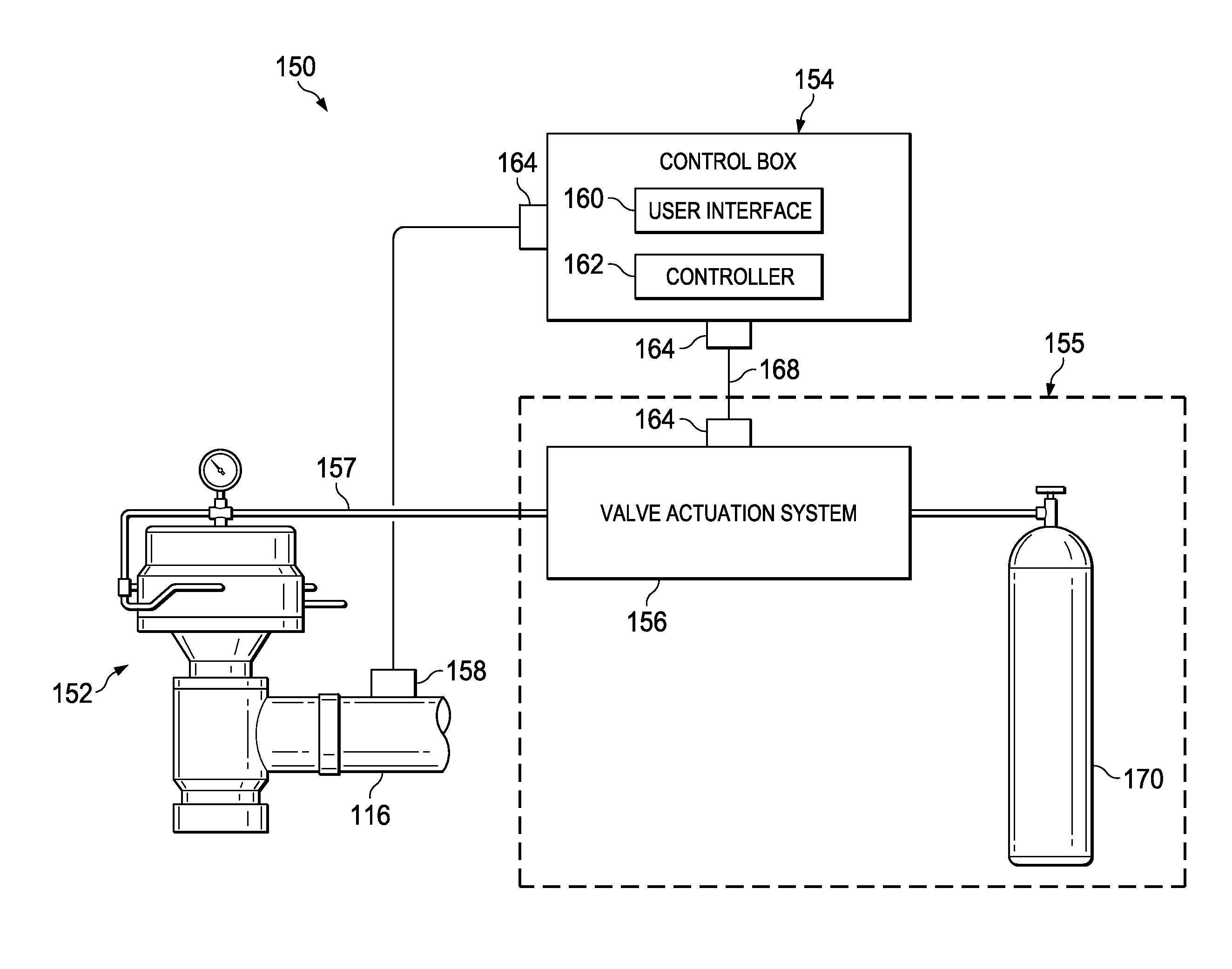
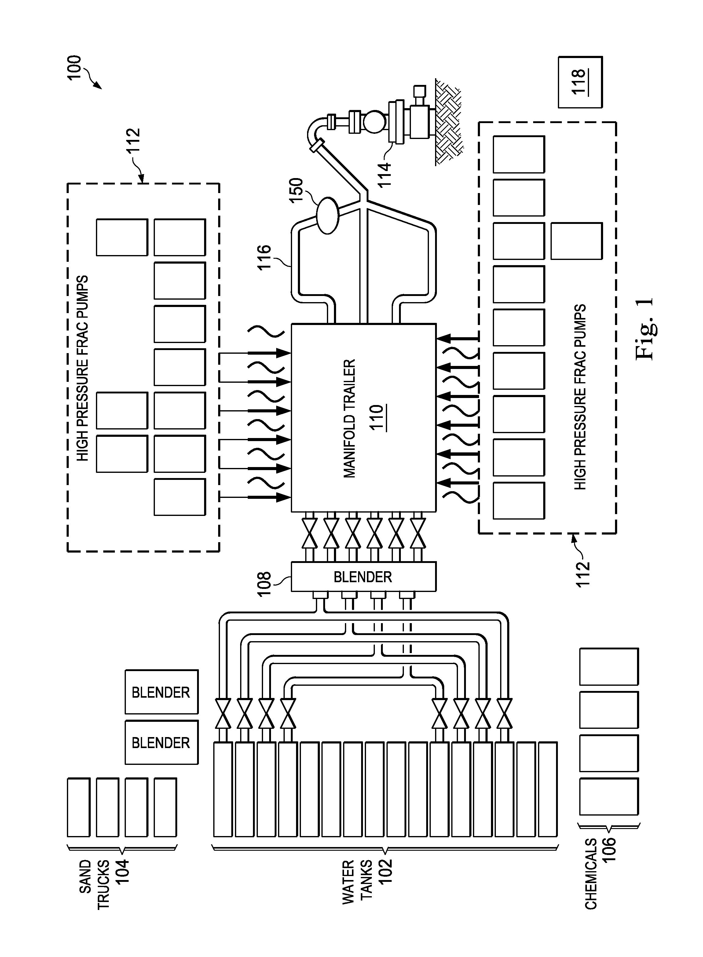
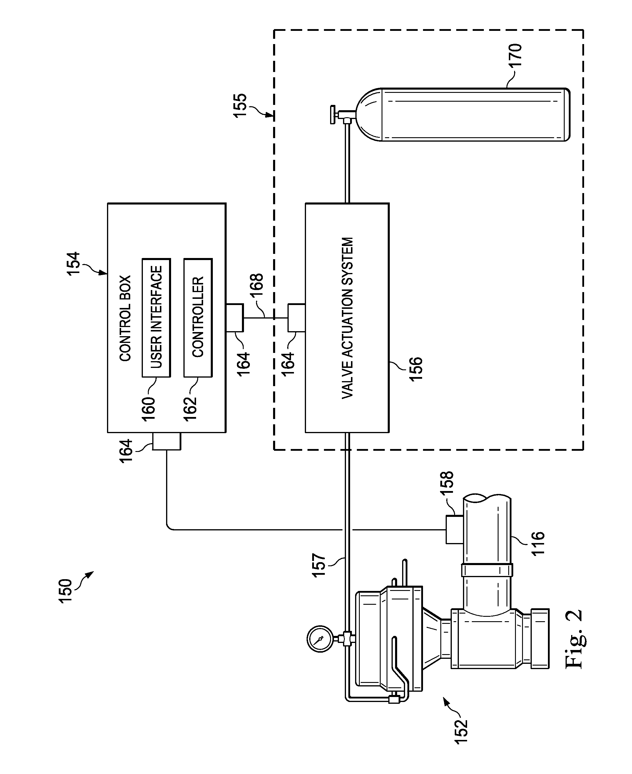
[0057]FIG. 1 illustrates an exemplary frac site incorporating the subject matter of the present disclosure. The frac site, referenced herein by the numeral 100, includes water trucks 102, sand trucks 104, chemicals 106, a blender 108, a manifold trailer 110, and high pressure frac pumps 112. The water, sand, and chemicals are introduced into the blender 108 to create slurry referenced herein as a fracturing or fracing fluid. The fracing fluid is introduced into the manifold trailer 110 and fed from the manifold trailer to high pressure frac pumps 112.

[0058]The manifold trailer 110 includes a low pressure section and a high pressure section. The low pressure section transfers low pressure from the blender 108 to the frac pumps 112. The high pressure section transfers the fracing fluid from the frac pumps 112 to a wellhead 114. The high pressure frac pumps 112 receive the mixed fluid from the manifold trailer 110 through a suction manifold and energize the fluid through the power end / ...


PUM


Abstract

A pressure relief valve system for use in a downhole operation may include a pressure relief valve configured to relieve pressure from high pressure tubing extending between a pump and a wellhead, and may include a sensor operably disposed to detect pressure in the high pressure tubing. The pressure relief valve system also may include a controller having a pressure threshold stored therein. The controller may be configured to receive data from the sensor and compare the detected pressure to the stored pressure threshold. A valve actuation system may be in communication with the pressure relief valve and in communication with the controller. The valve actuation system may be configured to change the state of the pressure relief valve from a closed state to an open state in response to a command signal from the controller.

Description

CROSS-REFERENCE TO RELATED APPLICATIONS[0001]This application is a continuation-in-part of U.S. patent application Ser. No. 13 / 886,771, filed May 3, 2013, which claims priority to and the benefit of the filing date of U.S. patent application No. 61 / 684,394, filed Aug. 17, 2012, the entire disclosures of which are hereby incorporated herein by reference.TECHNICAL FIELD[0002]This disclosure relates in general to a valve control system and method and, in particular, to an automated relief valve control system and method.BACKGROUND OF THE DISCLOSURE[0003]Hydraulic fracturing to stimulate a subterranean formation includes injecting a fracturing fluid through a wellbore into the formation at a pressure and flow rate at least sufficient to overcome the pressure of the reservoir and extend fractures into the formation. A high pressure line directs the fracturing fluid through a wellhead and into the wellbore. The fracturing fluid is a mixture of a liquid and a media, and is typically inject...

Claims


Application Information

Patent Timeline
Patent Type & Authority Applications(United States)
IPC IPC(8): E21B43/26
CPCE21B43/26E21B33/068E21B34/02F15B20/00F15B2211/50536F15B2211/50554E21B43/2607
Inventor BACA, MATTHEW S.WITKOWSKI, BRIAN C.
Owner SPM OIL & GAS INC
Why Eureka
Try Eureka