

Pneumatic nailer comprising a manually actuatable trigger and a contact feeler
- Summary
- Abstract
- Description
- Claims
- Application Information
AI Technical Summary
Benefits of technology
Problems solved by technology
Method used
Image

Examples
Embodiment Construction
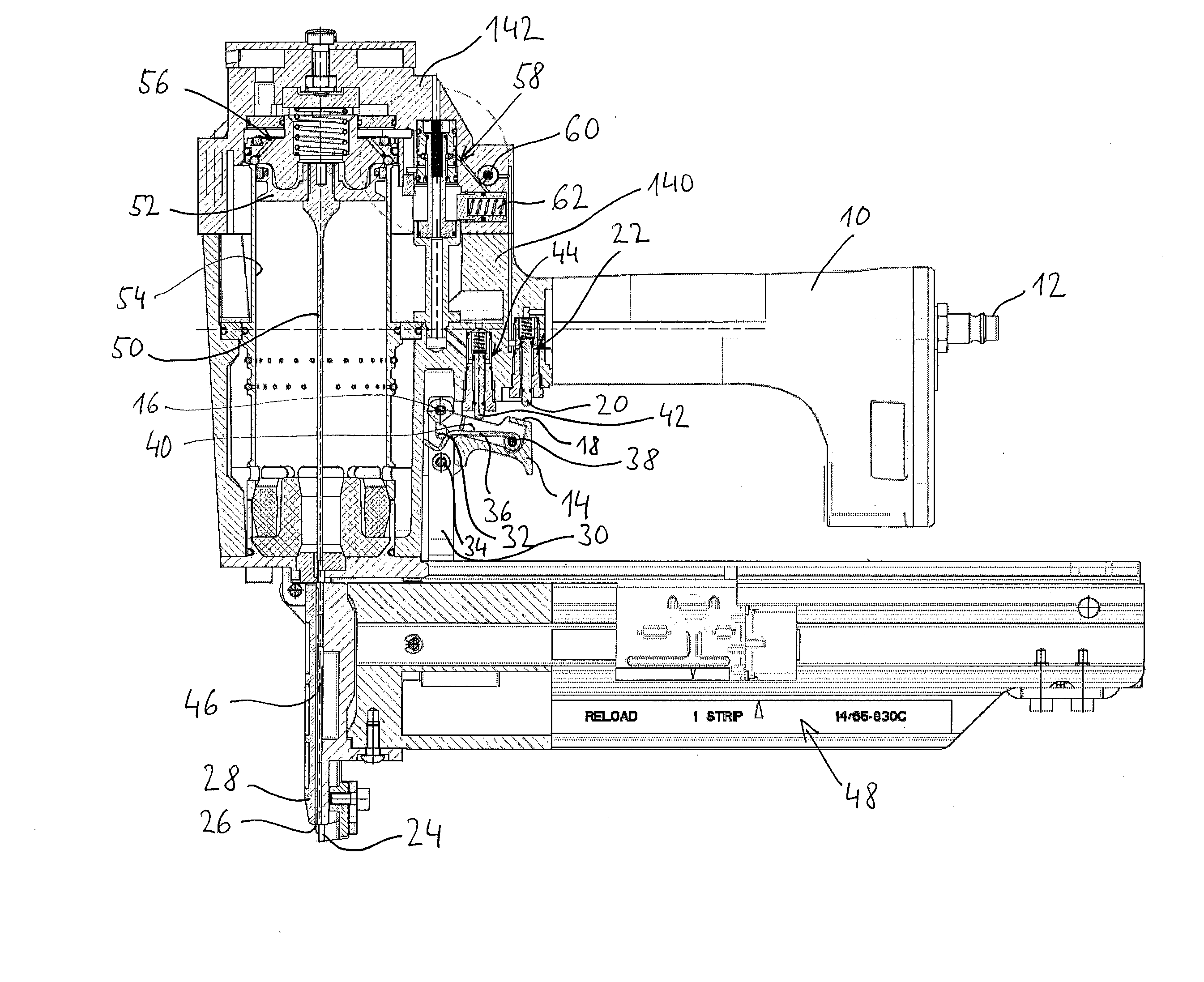
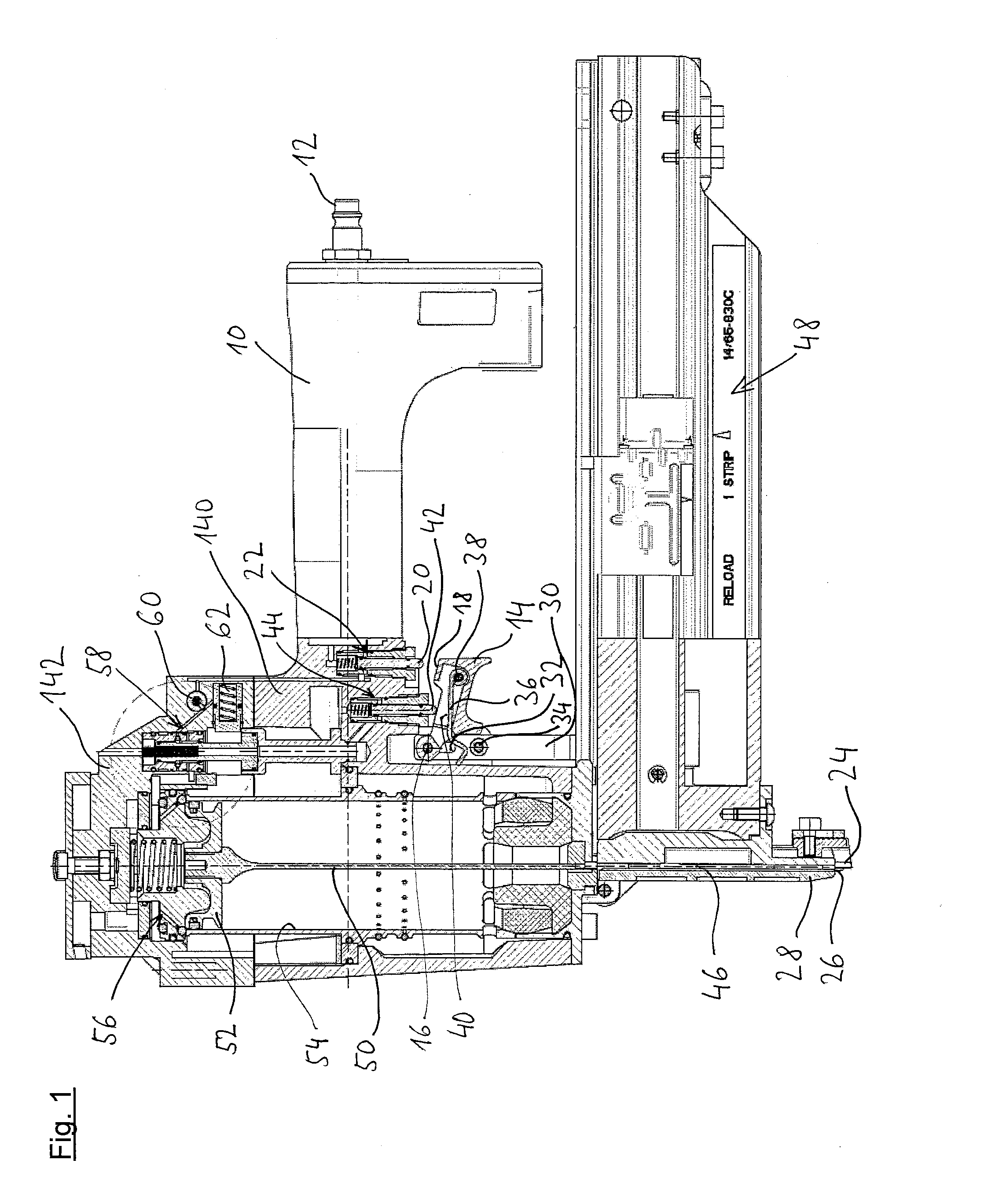
[0048]Firstly, with reference to FIG. 1, the most essential elements of the pneumatic nailer are shown partially in the manner of an overview. The pneumatic nailer has a handle 10, a central compressed air connection 12 being arranged at the rear end thereof The handle 10 is located on a lower housing part 140 which is closed at the top by a housing cap 142.
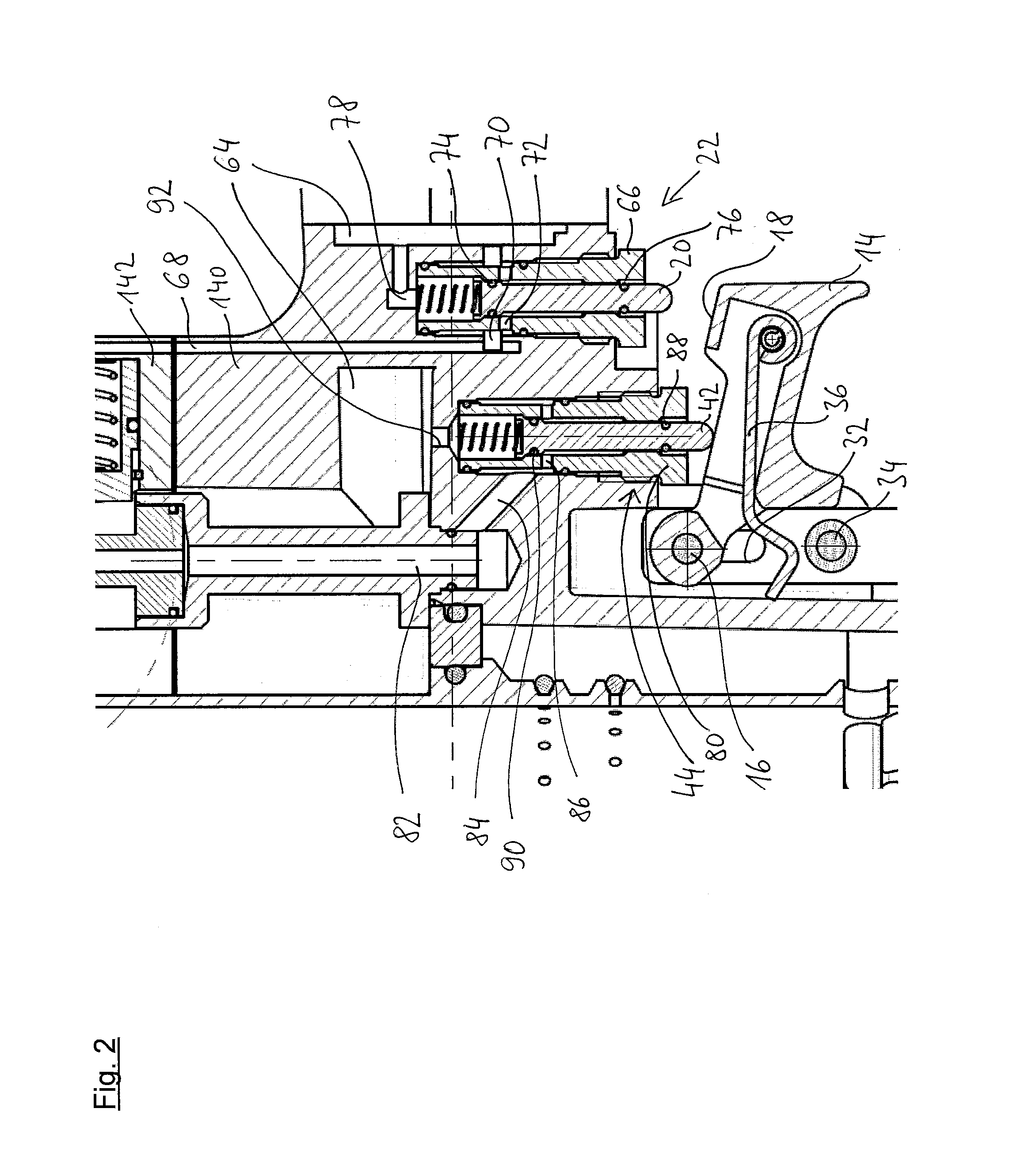
[0049]The manually actuatable trigger 14 is pivotably mounted about a pivot axis 16 on the housing of the pneumatic nailer and arranged such that it can be actuated comfortably by the index finger of a user holding the pneumatic nailer by the handle 10. During this actuation, a switching surface 18 arranged on the upper face of the trigger 14, comes to bear against a switching pin 20 of a second control valve 22, displaces the switching pin 20 upward and as a result activates the second control valve 22. As this activation of the second control valve 22 is effected immediately by the switching surface 18 arranged fixedly on the t...
PUM
| Property | Measurement | Unit |
|---|---|---|
| Time | aaaaa | aaaaa |
| Time | aaaaa | aaaaa |
| Pressure | aaaaa | aaaaa |
Abstract
Description
Claims
Application Information