Touch panel

Active Publication Date: 2015-03-26
HENGHAO TECH CO LTD
View PDF4 Cites 2 Cited by
  • Summary
  • Abstract
  • Description
  • Claims
  • Application Information

AI Technical Summary

Benefits of technology

The objective of this patent is to create a touch panel that reduces the appearance of traces and increases optical clarity. Additionally, it aims to make the touch panel pass more stringent test standards.

Problems solved by technology

The gap, however, can result in a trace phenomenon when users look at the touch panel 100.
Moreover, the touch panel 100 of the conventional layout as shown in FIG. 1 tends to be ill-adapted to stringent environments because of an incapability of sustaining high temperature and high humidity for a long time.

Method used


Image

  • Touch panel
  • Touch panel
  • Touch panel

Examples


Embodiment Construction

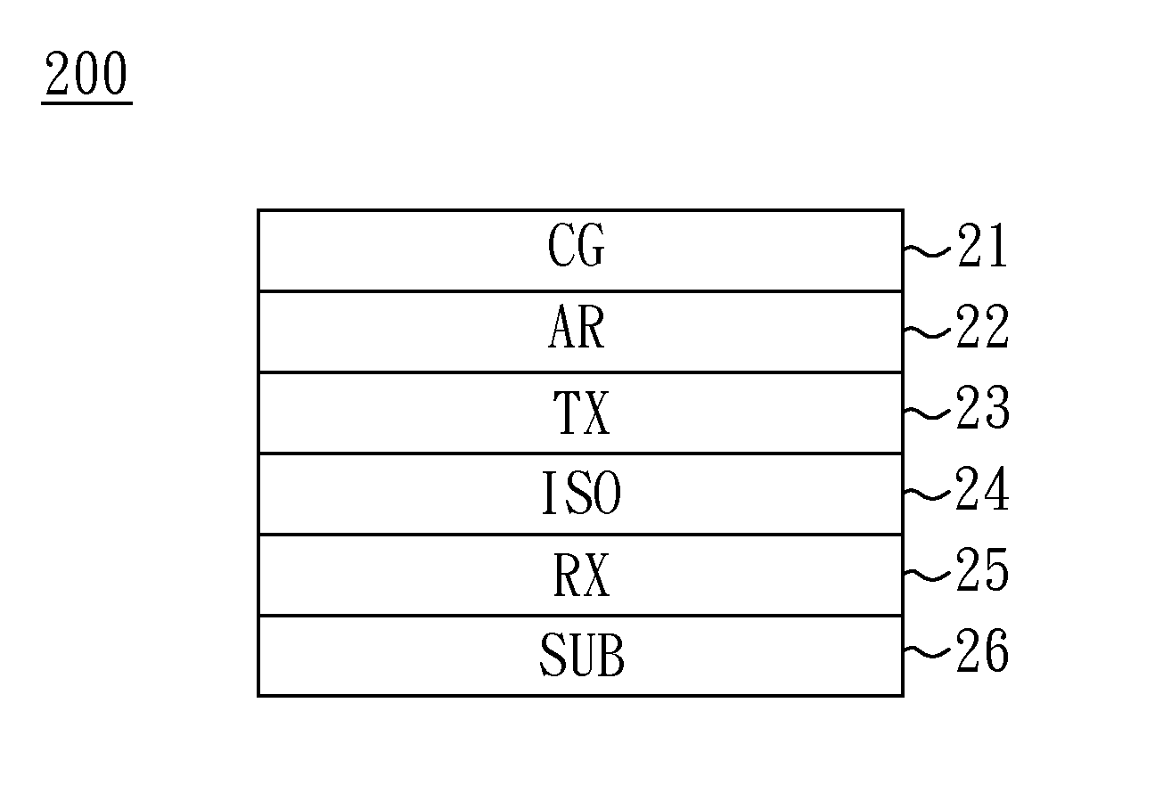
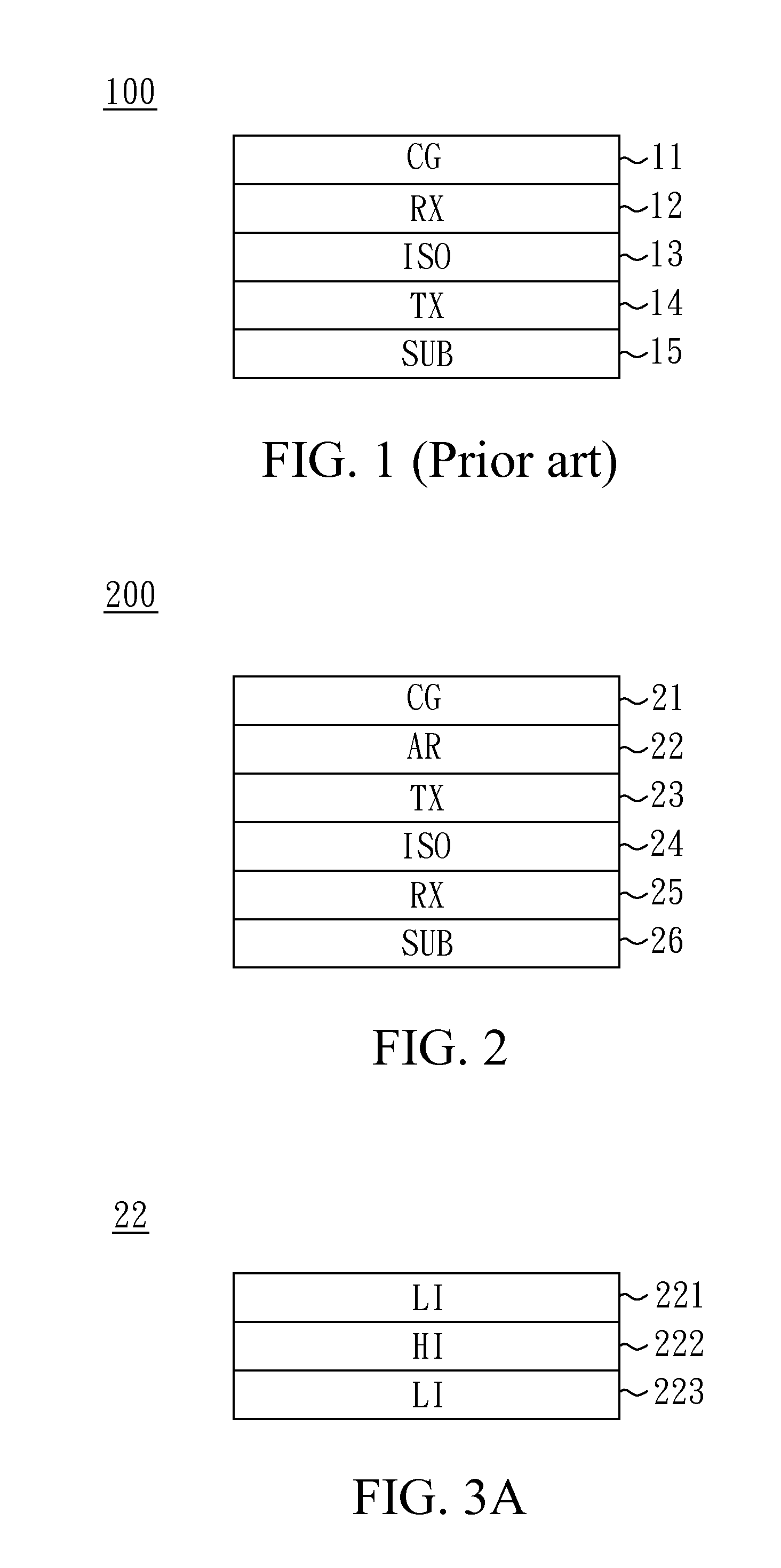
[0019]FIG. 2 shows a cross-sectional view of a touch panel 200 according to a first embodiment of the present invention. In the specification, “above” or “top” points toward a touch position, and “below” or “bottom” points opposite the touch position or points toward a display module (not shown), such as a liquid crystal display module. Only primary composing layers of the touch panel 200 are shown in the figures. A person skilled in the pertinent art could modify the shown structure by inserting further layers, when needed.

[0020]In the embodiment, the touch panel 200 includes, from top to bottom, a transparent cover (CG) layer 21, an anti-reflective (AR) layer 22, a transmit (TX) layer 23, an isolation (ISO) layer 24, a receive (RX) layer 25 and a transparent substrate (SUB) 26. In one embodiment, the transmit layer 23 (e.g., indium tin oxide (ITO) film) is formed on a bottom of the transparent cover layer 21 (e.g., cover glass) via the anti-reflective layer 22, and the receive lay...


PUM


Abstract

A touch panel includes dummy electrodes, disposed in a transmit electrode layer or a receive electrode layer whichever is below an isolation layer. In one embodiment, an anti-reflective layer includes at least one composite refractive-index three-layer structure. In another embodiment, the receive electrode layer is disposed below the isolation layer, and the receive electrode layer and the dummy electrodes are electrically coupled to a same electric potential.

Description

BACKGROUND OF THE INVENTION[0001]1. Field of the Invention[0002]The present invention generally relates to a touch panel, and more particularly to a touch panel with dummy electrodes.[0003]2. Description of Related Art[0004]A touch screen is an input / output device that adopts sensing technology and display technology, and is mainly composed of a touch panel and a liquid crystal display module. FIG. 1 shows a cross-sectional view of a conventional touch panel 100, which includes, from top to bottom, a transparent cover (CG) layer 11, a receive (RX) layer 12, an isolation (ISO) layer 13, a transmit (TX) layer 14 and a transparent substrate (SUB) 15. The receive layer 12 is commonly disposed above the isolation layer 13 (while the transmit layer 14 is disposed below the isolation layer 13) in the conventional touch panel 100 to prevent sensing receive signal from being affected by the liquid crystal display module.[0005]The receive layer 12 and the transmit layer 14 of the touch panel ...

Claims


Application Information

Patent Timeline
IPC IPC(8): G06F3/041
CPCG06F3/041G06F3/044G06F3/0412G06F3/0445G06F3/0448G02F1/13338G06F2203/04103
Inventor CHEN, CHI-AN
Owner HENGHAO TECH CO LTD
Why Eureka
Try Eureka