Check patentability & draft patents in minutes with Patsnap Eureka AI!

Image processing device, image capturing apparatus, and image processing method

a technology of image processing and image capturing apparatus, which is applied in the direction of image enhancement, instruments, optical elements, etc., can solve the problems of distance-measurement calculation depth information error due to color (wavelength),

Active Publication Date: 2015-04-02
CANON KK
View PDF11 Cites 15 Cited by
  • Summary
  • Abstract
  • Description
  • Claims
  • Application Information

AI Technical Summary

Benefits of technology

The present invention provides an image processing device and method for obtaining a depth information image that represents the distribution of depth information about an object. The device / method uses a first image and a second image that have different degrees of blurring to extract signals from multiple groups of pixels in the image sensor. These signals are subsequently used to calculate the depth information image that represents the object's depth information. The technical effects of this invention include improved image quality and more accurate depth information for better object recognition and analysis.

Problems solved by technology

As a result, in the case where depth information is calculated by using a correlation between the sizes or the degrees of blur, the calculated depth information has an error due to a color (wavelength).
In other words, when depth information is calculated by using a DFD method or the like using a color image, a distance-measurement error due to a color (wavelength) occurs.

Method used


Image

  • Image processing device, image capturing apparatus, and image processing method
  • Image processing device, image capturing apparatus, and image processing method
  • Image processing device, image capturing apparatus, and image processing method

Examples


first embodiment

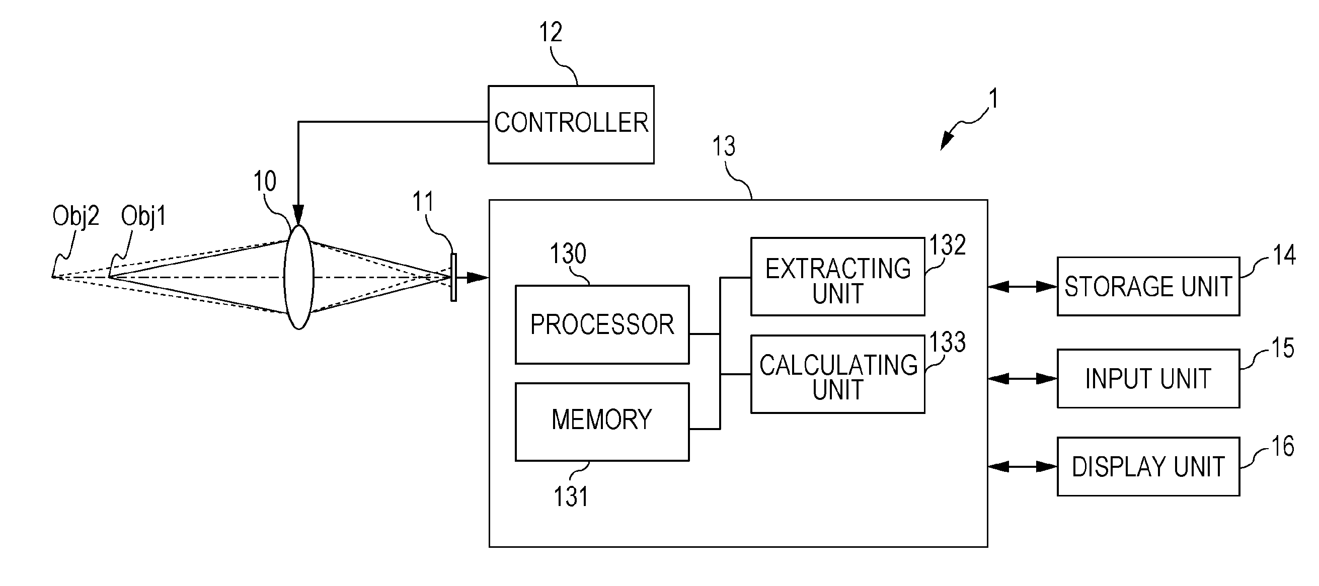
[0025]FIG. 1 is a schematic view illustrating an example of an image capturing apparatus 1 including an image processing device 13 according to a first embodiment. The image capturing apparatus 1 includes an image capturing optical system 10, an image sensor 11, a controller 12 of the image capturing optical system 10, the image processing device 13, a storage unit 14, an input unit 15, and a display unit 16.

[0026]FIG. 2A is a partial schematic view of the image sensor 11 according to the first embodiment. The image sensor 11 includes an image sensor 111 and a color filter 112. The color filter 112 is disposed on a side of the image sensor 111 on which light is incident. The image sensor 11 has a plurality of groups 113, each including pixels A, B, C, and D. Each of the pixels A, B, C, and D obtains color information about an object. Therefore, the color filter 112 has segmented regions, each of which allows a corresponding one of red, green, and blue light to pass therethrough. The...

second embodiment

[0057]The present embodiment differs from the first embodiment in that signals each corresponding to one of the pixels used to calculate the depth information are mixed signals each generated by mixing signals of different pixels of a corresponding one of the groups and in that an extracted image is generated from the mixed signals. Hereinafter, the difference from the first embodiment will be mainly described.

[0058]FIG. 4 is a schematic view illustrating an example of an image capturing apparatus 2 including an image processing device 23 according to the present embodiment. According to the present embodiment, the image processing device 23 of the image capturing apparatus 1 includes a generating unit 134, in addition to the processor 130, the memory 131, the extracting unit 132, and the calculating unit 133.

[0059]The generating unit 134 generates mixed signals each corresponding to one of the pixels that is used to calculate at least depth information by mixing signals respectivel...

third embodiment

[0072]The present embodiment differs from the second embodiment in that axial chromatic aberration and field curvature of extracted pixels are corrected. Hereinafter, the difference from the second embodiment will be mainly described.

[0073]FIG. 7 is a schematic view illustrating an image capturing apparatus 3 including an image processing device 33 according to the present embodiment. The image processing device 33 of the image capturing apparatus 3 according to the present embodiment includes a correcting unit 135, in addition to the processor 130, the memory 131, the extracting unit 132, the calculating unit 133, and the generating unit 134.

[0074]FIGS. 8A and 8B respectively illustrate the axial chromatic aberration and the field curvature of the image capturing optical system 10. The image capturing optical system 10 usually has axial chromatic aberration. The term “axial chromatic aberration” refers to a displacement of the focus position due to the difference in the wavelength ...


PUM


Abstract

An image processing device obtains a depth information image representing a distribution of depth information about an object on the basis of first and second images that have different degrees of blurring and that are captured by an image sensor including groups each including pixels that obtain different color information about the object. The image processing device includes an extracting unit configured to extract signals, each corresponding to one of the pixels of each group, from the groups and generate first and second extracted images respectively corresponding to the first and second images, and a calculating unit configured to calculate the depth information image from a difference in degree of blurring between the first and second extracted images. The signals each corresponding to one of the pixels of each group and extracted from the groups are signals corresponding to pixels that obtain the same color information.

Description

BACKGROUND OF THE INVENTION[0001]1. Field of the Invention[0002]The present invention relates to an image processing device and an image capturing apparatus for obtaining a depth information image, which represents a distribution of depth information about an object, from a plurality of captured images. The present invention also relates to an image processing method for obtaining a depth information image, which represents a distribution of depth information about an object, from a plurality of captured images.[0003]2. Description of the Related Art[0004]Japanese Patent Laid-Open No. 01-167610 describes a “depth from defocus” (DFD) method for obtaining the distance to an object in the depth direction by using a two-dimensional image of the object captured by an image capturing apparatus. In the DFD method, a plurality of images that have different degrees of blurring are obtained by controlling the shooting conditions (also referred to as the shooting parameters) of an image captur...

Claims


Application Information

Patent Timeline
IPC IPC(8): G01B11/22G06K9/46
CPCG06K9/4652G01B11/22G06T2207/10004G06T2207/10148G02B7/365G06T7/571G06T2207/10144H04N23/676H04N23/673H04N23/743H04N23/843H04N25/134
Inventor ISHIHARA, KEIICHIRO
Owner CANON KK
Features
  • R&D
  • Intellectual Property
  • Life Sciences
  • Materials
  • Tech Scout
  • Unparalleled Data Quality
  • Higher Quality Content
  • 60% Fewer Hallucinations
Learn More