Hand-carried taping machine with non-powered guide system

a guide system and hand-carried technology, applied in the field of hand-carried taping machines, can solve the problems of labor-intensive hand taping operation, large end windings, and large end windings

Active Publication Date: 2015-04-09
GENERAL ELECTRIC CO
View PDF5 Cites 8 Cited by
  • Summary
  • Abstract
  • Description
  • Claims
  • Application Information

AI Technical Summary

Benefits of technology

[0003]A first aspect of the disclosure provides a hand-carried taping machine for taping an elongated object, the hand-carried taping machine comprising: a body defining an opening to one side of the body that extends in an outward direction from a closed inner end, wherein an application axis extends generally perpendicular to the outward direction of the opening in the body; a powered gear set operably coupled to the body and powered by a drive system; an applicator head including a substantially C-shaped gear in meshing engagement with the powered gear set such that the substantially C-shaped gear rotates about the application axis under control of the drive system, and a tape reel mount for rotatably mounting a reel of tape on the substantially C-shaped gear for rotation about the application axis and application of the tape to the elongated object; and a non-powered guide system operably coupled to the body for guiding the applicator head along the elongated object with transient engagement with the elongated object such that the elongated object is maintained in a vicinity of the reel of tape.
[0004]A second aspect of the disclosure provides a hand-carried taping machine for taping an elongated object, the hand-carried taping machine comprising: a body defining an opening to one side of the body that extends in an outward direction from a closed inner end, wherein an application axis extends generally perpendicular to the outward direction of the opening in the body; a powered gear set operably coupled to the body and powered by a drive system; an applicator head including: a substantially C-shaped gear in meshing engagement with the powered gear set such that the substantially C-shaped gear rotates about the application axis under control of the drive system, a tape reel mount for rotatably mounting a reel of tape on the substantially C-shaped gear for rotation a

Problems solved by technology

The end windings are typically too large or clumsy to move.
In this setting, the inability to control overlap/placement of the tape with current hand held taping machines while also allowing degrees of motion/freedom to wrap non-linear paths prevents the use of the machines.
In terms of generator end windings, the hand taping operation is a labor intensive process that is often on the critical p

Method used


Image

  • Hand-carried taping machine with non-powered guide system
  • Hand-carried taping machine with non-powered guide system
  • Hand-carried taping machine with non-powered guide system

Examples


Embodiment Construction

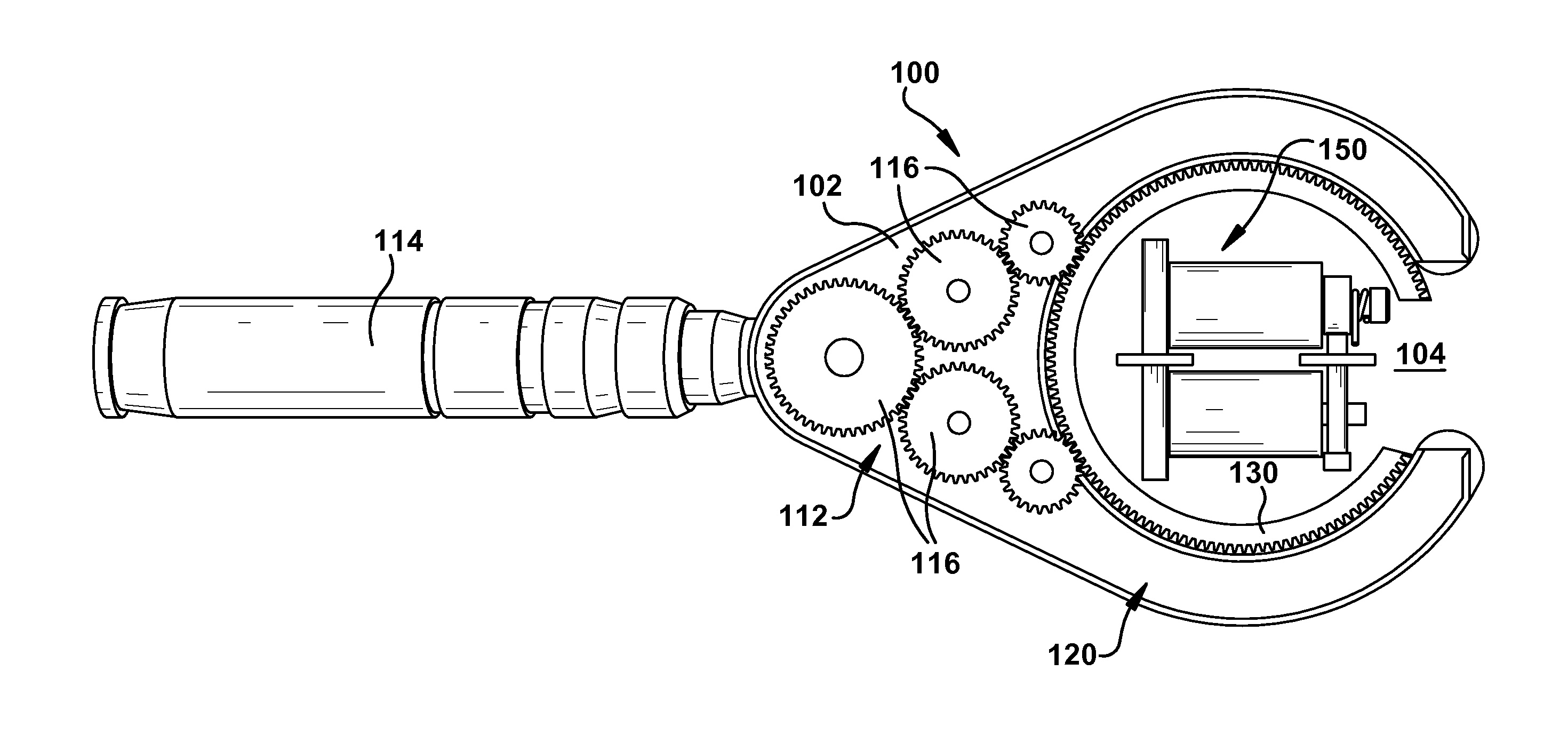
[0018]As indicated above, the disclosure provides a hand-carried taping machine with a non-powered guide system. The hand-carried taping machine provides the ability to control overlap / placement of the tape with a hand held device while also allowing degrees of motion / freedom to wrap non-linear paths.

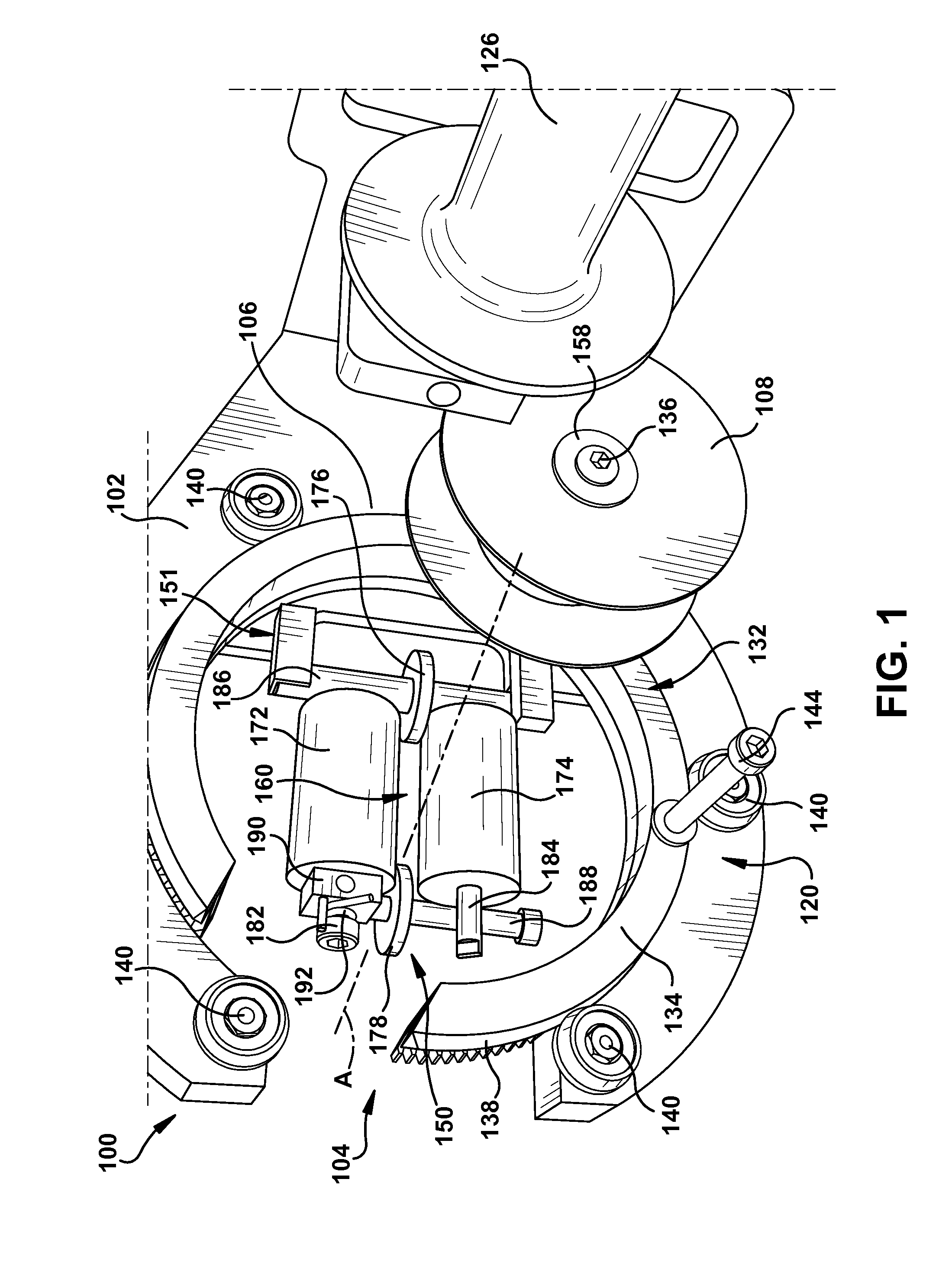
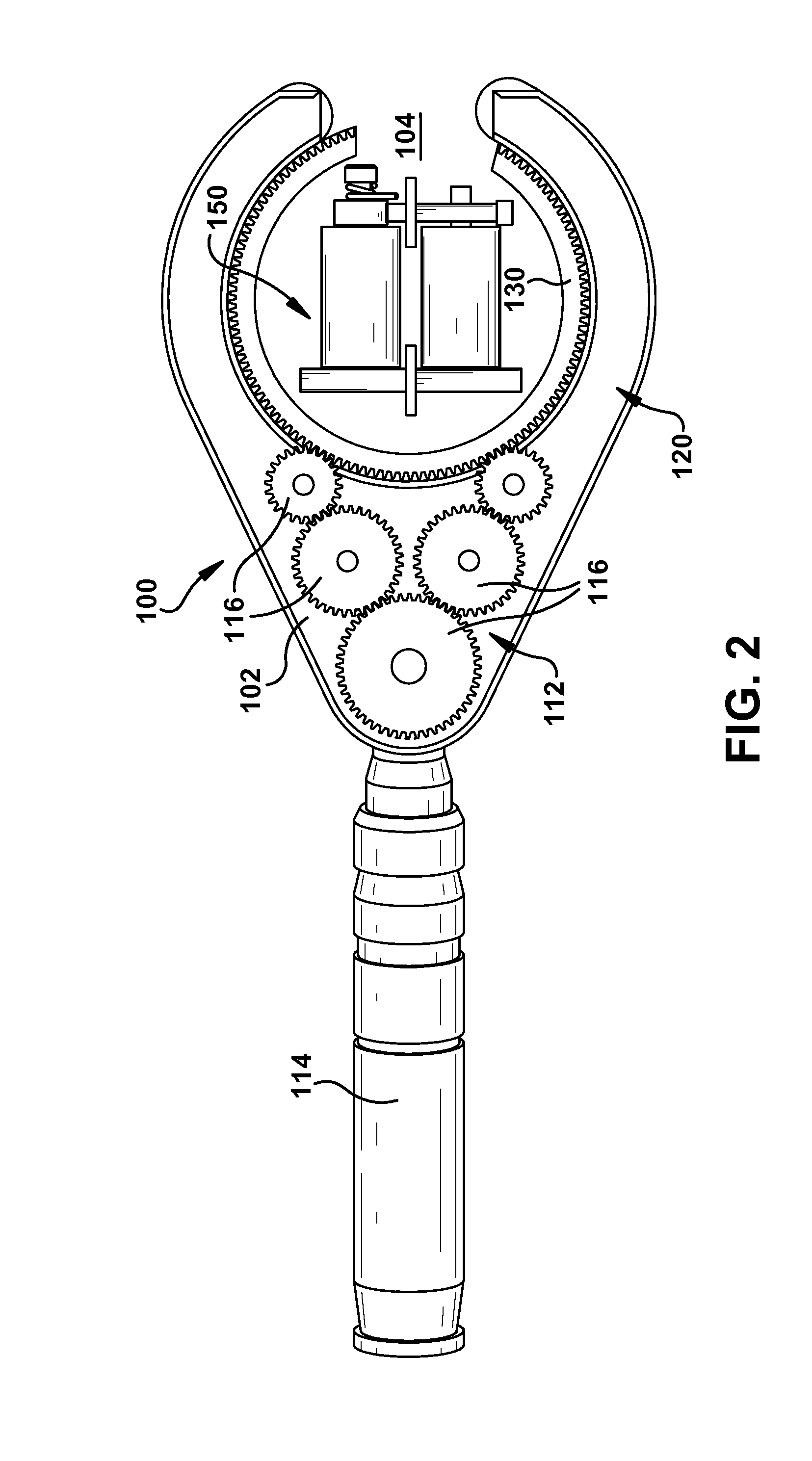
[0019]Referring to FIG. 1, a front perspective view of a hand-carried taping machine 100 for taping an elongated object 101 (FIGS. 6-7) according to embodiments of the invention is illustrated. Hand-carried taping machine 100 generally includes a body 102, a powered gear set 112 (FIG. 2 only), a drive system 114 (FIGS. 2, 4 and 5), an applicator head 120 for deploying a tape from a reel of tape 108, and a non-powered guide system 150. Taping machine 100 is “hand-carried” in that its weight is carried by a user excepting any weight supported by elongated object 101 to be taped, i.e., there are no overhead or table support systems and the machine is highly portable. In FIGS. 6 and 7, elon...


PUM

PropertyMeasurementUnit
Timeaaaaaaaaaa
Angleaaaaaaaaaa
Tensionaaaaaaaaaa

Abstract

A hand-carried taping machine for taping an elongated object is disclosed. The machine includes a powered gear set operably coupled to a body and powered by a drive system. An applicator head includes a substantially C-shaped gear in meshing engagement with the powered gear set such that the substantially C-shaped gear rotates about an application axis under control of the drive system, and a tape reel mount for rotatably mounting a reel of tape on the substantially C-shaped gear for rotation about the application axis and application of the tape to the elongated object. A non-powered guide system operably couples to the body for guiding the applicator head along the elongated object with transient engagement with the elongated object such that the elongated object is maintained in a vicinity of the reel of tape.

Description

BACKGROUND OF THE INVENTION[0001]The disclosure relates generally to taping machines, and more particularly, to a hand-carried taping machine including a non-powered guide system.[0002]Applying tape to an object is performed for a number of reasons. Various automated tape applying machines, some of which are hand-carried, exist for taping various objects. One illustrative industrial taping operation that is typically performed by hand, however, includes taping the rotor end windings of a generator with insulating (e.g., fiberglass) tape. The end windings, while having a uniform cross-section, typically have an extensive length that curves at different degrees of severity along its length. The end windings are typically too large or clumsy to move. In this setting, the inability to control overlap / placement of the tape with current hand held taping machines while also allowing degrees of motion / freedom to wrap non-linear paths prevents the use of the machines. Consequently, while tap...

Claims


Application Information

Patent Timeline
IPC IPC(8): B65H81/00B65H79/00B29C70/54B29C70/30
CPCB65H81/00B29C70/30B65H2404/10B29C70/54B65H79/00B65H54/2896B65H57/14B65H2701/37B65H81/08B65H81/04B65H81/06B65H81/02B65H2403/30B65H2403/40B65B27/10B65B27/105B65C3/02H01B13/01281H01B13/08H01B13/0808H01B13/0833H01B13/0816H01B13/0825
Inventor WORD, JACOB WADECARBERRY, ADAM SCOTTHATLEY, RICHARD MICHAELOLLE, MICHAEL STEVEN
Owner GENERAL ELECTRIC CO
Why Eureka
Try Eureka