Interlock pipe connection

a technology of interlocking pipes and pipes, applied in the direction of hose connections, couplings, borehole/well accessories, etc., can solve the problems of unintended separation downhole, drilling operations must be suspended,

Active Publication Date: 2015-04-09
NABORS IND INC
View PDF25 Cites 14 Cited by
  • Summary
  • Abstract
  • Description
  • Claims
  • Application Information

AI Technical Summary

Benefits of technology

[0008]The present disclosure provides for a pipe joint for use in joining tubular members. The pipe joint may include a box formed in an end of a first tubular member, the box formed in the interior surface of the first tubular member, the box including internal threads and internal lands, the internal threads positioned in radial segments and separated by the internal lands, the lands being generally cylindrical segments having inner diameter larger than the largest outer diameter of the largest thread. The pipe joint may also include a pin formed in an end of a second tubular member, the pin formed in the exterior surface of the second tubular member, the pin including external threads and external lands, the external threads positioned in radial segments and separated by the external lands, the lands being generally cylindrical segments having outer diameter smaller than the smallest outer diameter of the smallest thread. The widths and positions of the external threads of the pin may be positioned to correspond with those of the internal lands of the box, and the widths and positions of the external lands of the pin may be positioned to correspond with those of the internal threads of the box when the box is inserted into the pin. The external threads of the box and the internal threads of the pin may be positioned to mesh and tighten the box to the pin and provide a fluid seal between the first and second tubular member.
[0009]The present disclosure further provides for a pipe joint for use in joining tubular members. The pipe joint may include a box formed in an end of a first tubular member, the box formed in the interior surface of the first tubular member, the box including stepped internal threads and internal lands, the stepped internal threads positioned in radial segments, the stepped internal threads arranged in groups of a generally repeating pattern of thickness ascending order, the groups separated by the internal lands, the lands being generally cylindrical segments having inner diameter larger than the largest outer diameter of the largest thread. The pipe joint may also include a pin formed in an end of a second tubular member, the pin formed in the exterior surface of the second tubular member, the pin including stepped external threads and external lands, the stepped external threads positioned in radial segments, the stepped external threads arranged in groups of a generally repeating pattern of thickness ascending order, the groups separated by the external lands, the lands being generally cylindrical segments having outer diameter smaller than the smallest outer diameter of the smallest thread. The widths and positions of the largest stepped external threads of the pin may be positioned to correspond with those of the internal lands of the box, and the widths and positions of the external lands of the pin may be positioned to correspond with those of the largest stepped internal threads of the box when the box is inserted into the pin. The stepped external threads of the box and the stepped internal threads of the pin may be positioned to mesh and tighten the box to the pin and provide a fluid seal between the first and second tubular member.
[0010]The present disclosure further provides for a method of making up a pipe joint. The method may include providing a first tubular member, the first tubular member including a box formed in the interior surface of an end of the first tubular member, the box including internal threads and internal lands, the internal threads positioned in radial segments and separated by the internal lands, the lands being generally cylindrical segments having inner diameter larger than the largest outer diameter of the largest thread; providing a second tubular member, the second tubular member including a pin formed in the exterior surface of an end of the second tubular member, the pin including external threads and external lands, the external threads positioned in radial segments and separated by the external lands, the lands being generally cylindrical segments having outer diameter smaller than the smallest outer diameter of the smallest thread, the external threads of the box and the internal threads of the pin positioned to mesh; aligning the box and the pin so that the widths and positions of the external threads of the pin positioned to correspond with those of the internal lands of the box, and the widths and positions of the external lands of the pin positioned to correspond with those of the internal threads of the box; inserting the pin into the box; and rotating the pin.

Problems solved by technology

Such an unintended disconnection may result in costly and time-consuming “fishing” operations to retrieve the disconnected section of drill pipe, during which drilling operations must be suspended.
Additionally, if excess make-up torque is applied, material yielding in the threaded connections may cause damage to the tubulars which may result in, for example, unintended separation downhole.

Method used


Image

  • Interlock pipe connection
  • Interlock pipe connection
  • Interlock pipe connection

Examples


Embodiment Construction

[0025]It is to be understood that the following disclosure provides many different embodiments, or examples, for implementing different features of various embodiments. Specific examples of components and arrangements are described below to simplify the present disclosure. These are, of course, merely examples and are not intended to be limiting. In addition, the present disclosure may repeat reference numerals and / or letters in the various examples. This repetition is for the purpose of simplicity and clarity and does not in itself dictate a relationship between the various embodiments and / or configurations discussed.

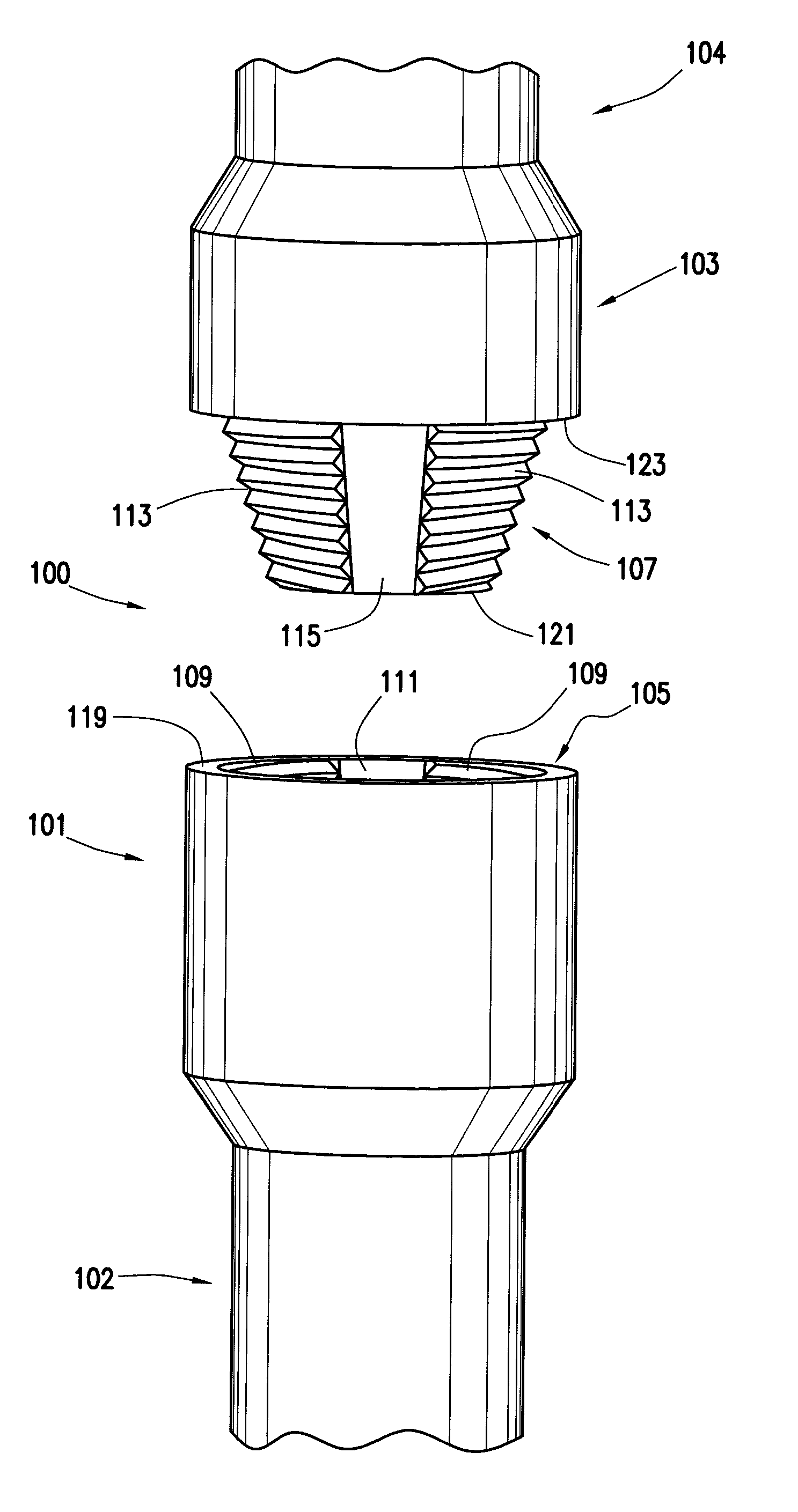
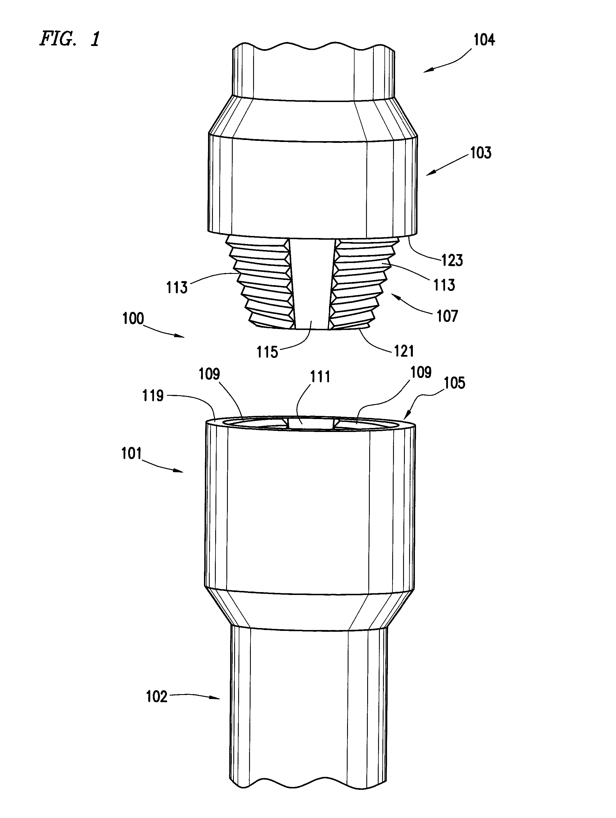
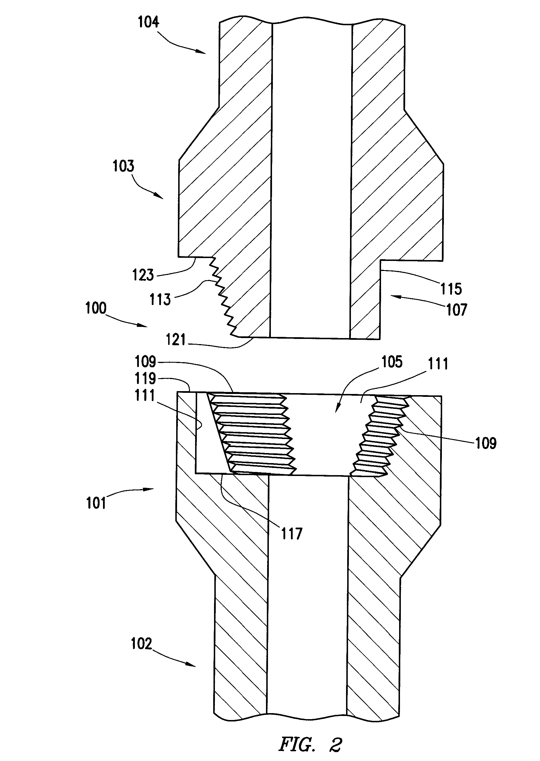
[0026]In one embodiment of the present disclosure, an interrupted thread box and pin connection is described. As illustrated in FIGS. 1-4, an interrupted thread pipe joint 100 utilizes an interrupted thread box 101 and interrupted thread pin 103. Interrupted thread box 101 is formed as an end of a first tubular 102, and interrupted thread pin is formed as an end of a s...


PUM


Abstract

An interlock pipe joint includes a first and second tubular member. In some embodiments, an interrupted thread box and pin make up the interlock pipe joint. In other embodiments, a stepped interrupted thread box and pin make up the interlock pipe joint. In other embodiments, a twist-lock box and pin make up the interlock pipe joint. In some embodiments, an external or internal bushing is provided. In a method of operation, the first tubular member is inserted into the second tubular member by an axial insertion followed by a rotation to lock the pipe joint.

Description

CROSS-REFERENCE TO RELATED APPLICATIONS[0001]This application is a non-provisional application which claims priority from U.S. provisional application No. 61 / 886,146, filed Oct. 3, 2013.TECHNICAL FIELD[0002]1. Field of the Disclosure[0003]The present disclosure relates to coupling lengths of pipe. The present disclosure relates particularly to coupling lengths of pipe used to make up a string for downhole applications.[0004]2. Background of the Disclosure[0005]In many stages of the drilling and completion of an oil and gas well, tubular members may be coupled end-to-end to form what is known as a string. For the purposes of this disclosure, the term “drill string” will be used to refer to any such string, including without limitation, drill strings, tool strings, casing strings, and completion strings. Typically, tubular members may be made up in approximately 30-90 foot segments, and include threaded couplings at each end. Commonly known as “box” and “pin” connections for the femal...

Claims


Application Information

Patent Timeline
Patent Type & Authority Applications(United States)
IPC IPC(8): E21B17/042F16L15/04E21B17/043F16L15/00E21B17/046
CPCE21B17/042F16L15/006F16L15/04E21B17/043E21B17/046F16L15/002F16L15/08F16L15/06F16L37/2445
Inventor MAGNUSON, CHRISABARCA, ENRIQUE
Owner NABORS IND INC
Why Eureka
Try Eureka