Interlock vessel for hyperbaric transfer system

a technology of interlocking vessel and transfer system, which is applied in the field of interlocking vessel for hyperbaric transfer system, can solve the problems of operator's attempt to open the air lock, serious risk of trauma to divers, permanent disabling injuries, etc., and achieve the effect of preventing undesirable rotation and facilitating air tight engagement of the door

Inactive Publication Date: 2010-02-18
BARTLETT ROBERT D
View PDF16 Cites 12 Cited by
  • Summary
  • Abstract
  • Description
  • Claims
  • Application Information

AI Technical Summary

Benefits of technology

[0029]In one embodiment one or both the inner door and / or the outer door can be equipped with latch assemblies for safely closing the doors to maintain an air tight environment.
[0031]In another embodiment is provided an interlock assembly that has a plurality of locking / latching safety locks which prevent an undesirable rapid venting of the decompression chamber wherein a diver and / or patient is situated.
[0033]In one embodiment one or both the inner door and the outer door can be provided with seals (such as sealing O-ring fitted on the inside surface of the respective door) to facilitate the air tight engagement of the door with the body of the portal.
[0034]In one embodiment is provided a locking ring mounted at the outside edge of the vessel or portal allowing at least one locking bar to selectively extend therethrough (from the rear) to prevent undesirable rotation and opening of the outer door at a time when the vessel or portal is at an elevated pressure.
[0053]In one embodiment rotation of the outer door causes the door to tighten (shut more securely and seal) relative to the interior of the portal.
[0061]In one embodiment the inner door includes a floating connection with its hinge, this floating connection assisting in aligning the door with the interior opening of the portal. In one embodiment the inner door includes a centrally protruding section which can assist in aligning concentrically the inner door with the interior opening of the portal.

Problems solved by technology

For example, deep sea diving, whether for pleasure or work, is associated with a serious risk of trauma to the divers.
Without proper treatment, major problems from diving accidents, most commonly decompression sickness (or the “bends”) and Air Embolism, can lead to permanent disabling injuries and in some instances be fatal.
In keeping with this objective the problem arises of keeping the gas mixtures constant within the vessels of the transfer system.
One hazard for conventional locks for closures is that the operator can attempt to open the air lock while the door is under pressure.
As a consequence of this pressure differential, the door can be forced open very fast and the operator can be injured or the person inside the chamber can be injured by the inner door swinging open explosively.
Even relatively small pressure differentials between the interior of the portals and the area where the closure is being opened can cause large forces on the closures and cause them to open fast causing injury.
Another potential problem with two-ring closures (or doors) relates to the door support allowing the door to both “swing out” (e.g., open and close) but also rotate about its axis (for locking / sealing and unlocking / unsealing).
However, these bearings eventually wear, and such wear allows changes in concentric alignments of the door relative to the locking ring.
For a closure where human life depends on its proper operation a concentricity misalignment of the door which leads to a gap and possible extrusion failure is unacceptable.
These “vent-plug-on-chains interlocks” can restrict opening of the door, but they are slow and awkward.
Another problem with dive chamber air locks relates to the operation of the inner closure or door.
However, dive chambers are not always in use and pressurized and when on ships, and when not pressurized dive chambers can be subjected to large jerking motions (such as wave action) causing the “unlocked” inner door to swing open and shut causing damage.
During periods in which a dive chamber is subjected to large jerking motions, an “unsecured inner door” can bounce open and closed, which can cause damage to the inner door, O-ring, and / or portal.
Furthermore, if the inner door is somehow opened when the interior of the dive chamber is pressurized but unoccupied, a person standing outside the dive chamber would be unable to reach through the outer door and grab hold and close the inner door.
However, even assuming that the interior door can be reached from the exterior, attempting to close the inner door from the exterior is very dangerous because the increased interior pressure can cause the interior door to slam shut very quickly, which slamming shut can harm the person attempting to close.
However, swing bolts or clamping latches have the disadvantage of continuing to hold shut the inner door even where the portal pressure (or exterior pressure) is substantially greater than the interior dive chamber pressure.
A trapped high differential pressure behind the inner door risks this door being slammed open and harming a person in the interior of the dive chamber—such as where the swing bolt or clamping latch is released (or fails) with a trapped high differential pressure behind the inner door.
Such a condition could lead to an explosive release of the inner door.
Another disadvantage with conventionally available air locks (or access portals) is their lack of dealing with the time delay between: (a) starting the venting process of the interior of the portal and (b) the finishing of the venting process.

Method used


Image

  • Interlock vessel for hyperbaric transfer system
  • Interlock vessel for hyperbaric transfer system
  • Interlock vessel for hyperbaric transfer system

Examples


Embodiment Construction

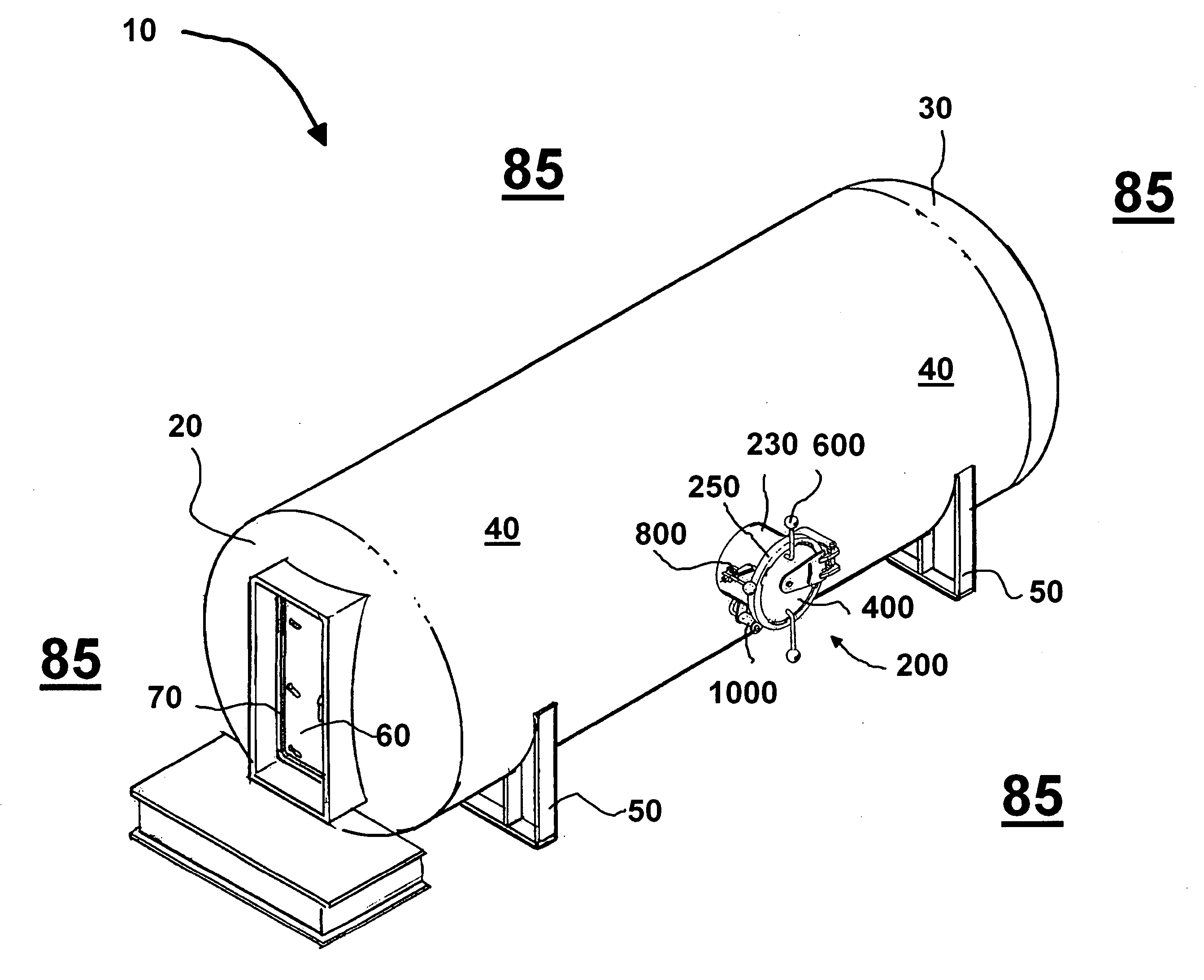
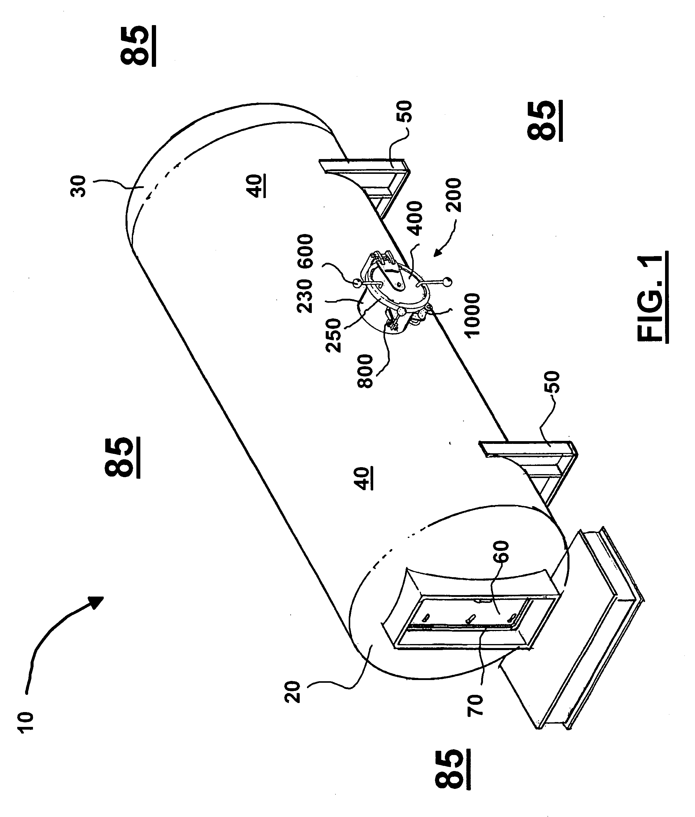
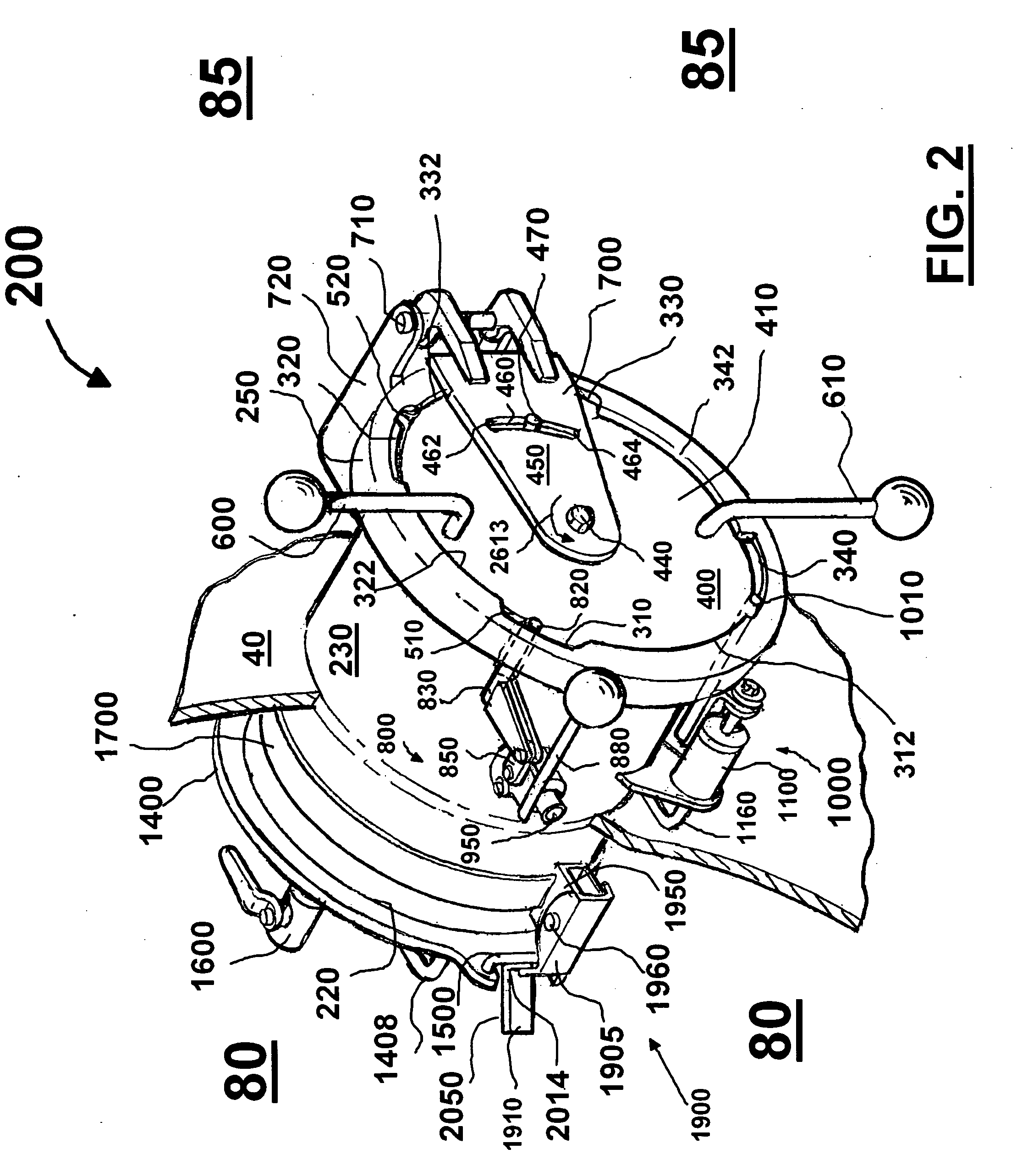
[0088]Turning now to the drawings in more detail an airlock assembly or portal is generally designated by numeral 200. In the following description, the terms “portal,”“airlock assembly,” interlock vessel,” and interlock assembly are used interchangeably. The portal 200 is designed to be used in a hyperbaric chamber (e.g., decompression chamber) 10 transfer system.

[0089]FIG. 1 is a perspective view of a decompression chamber 10 with air lock or portal 200. In one embodiment a decompression chamber 10 having a fluidly connected portal 200 is included. Decompression chamber 10 can include first end 20, second end 30, and side wall 40. Base 50 can be included to support chamber 10. For entering chamber 10 a door 60 can be provided. Door 60 can be sealed with conventionally available seal 70. Chamber 10 can have interior 80, and sidewall 40 can separate interior 80 from the exterior 85 (or ambient environment). Preferably, door 60 opens to the interior 80 of chamber 10.

[0090]As will be ...


PUM


Abstract

An interlock vessel having an air-tight body with opposing ends. A portion of the body is designed to fit into a decompression (hyperbaric) chamber, wherein a diver or a patient undergoing a decompression treatment is positioned. The opposing ends are closed by pivotally moveable doors and locking assemblies that retain the doors in a closed position until the pressure inside the decompression chamber and the exterior of the chamber can be equalized. The outer door has two locking systems: (a) an interlock system and (b) a safety / delay locking system. Both locking assemblies are manually operated.

Description

CROSS-REFERENCE TO RELATED APPLICATIONS[0001]This application is a continuation of PCT Application Serial No. PCT / US07 / 85471, filed Nov. 23, 2007, which was a continuation-in-part of U.S. patent application Ser. No. 11 / 893,174, filed Aug. 15, 2007, which application was a continuation-in-part of U.S. patent application Ser. No. 11 / 626,648, filed 24 Jan. 2007, and priority of each of the above referenced applications is hereby claimed.[0002]PCT Application Serial No. PCT / US07 / 85471, filed Nov. 23, 2007, is incorporated herein by reference.[0003]U.S. patent application Ser. No. 11 / 893,174, filed 15 Aug. 2007, is incorporated herein by reference.[0004]U.S. patent application Ser. No. 11 / 626,648, filed 24 Jan. 2007, is incorporated herein by reference.STATEMENT REGARDING FEDERALLY SPONSORED RESEARCH OR DEVELOPMENT[0005]Not applicableREFERENCE TO A “MICROFICHE APPENDIX”[0006]Not applicableBACKGROUND[0007]Hyperbaric and / or decompression chambers are used in many applications, and in many ...

Claims


Application Information

Patent Timeline
Patent Type & Authority Applications(United States)
IPC IPC(8): A61G10/00E06B7/00
CPCB63C11/32Y10T137/86308A61G10/026A62B9/02
Inventor BARTLETT, ROBERT D.
Owner BARTLETT ROBERT D
Why Eureka
Try Eureka