Ice shaver structure

Inactive Publication Date: 2015-04-09
HSU SHIH JUNG +1
View PDF10 Cites 6 Cited by
  • Summary
  • Abstract
  • Description
  • Claims
  • Application Information

AI Technical Summary

Benefits of technology

[0009]Therefore, it is a primary objective of the present invention to provide an ice shaver structure comprising a worm shaft with a worm gear installed on a side of the worm shaft, a resistance mechanism installed on the worm gear for providing the resistance to resist the rotation of the worm gear, su

Problems solved by technology

However, the aforementioned mechanism uses the elastic force produced by the compression of the spring Si to press the worm gear 18 against the worm shaft 11 in order to form the resistance, so that the worm gear 18 is situated at a relatively fixed status, and thus the friction produced between the worm shaft 11 and the worm gear 18 may wear out or damage the whole mechanism after a long time of use.
Therefore, the conventional ice shaver cannot adjust the falling displacement after the worm shaft 11 has rotated for one round, so that it cannot change the dense level of the shaved ice, and such ice shaver is lack of diversity.
However the aforementioned ice

Method used


Image

  • Ice shaver structure
  • Ice shaver structure
  • Ice shaver structure

Examples


Example

[0030]The present invention will become clearer in light of the following detailed description of an illustrative embodiment of this invention described in connection with the drawings. It is intended that the embodiments and drawings disclosed herein are to be considered illustrative rather than restrictive.

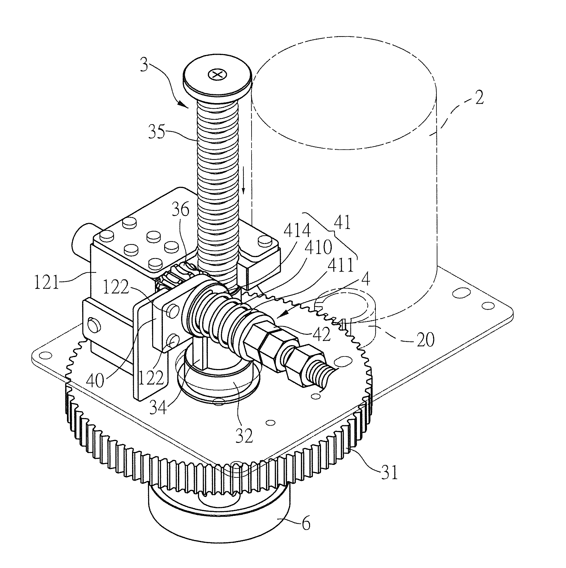
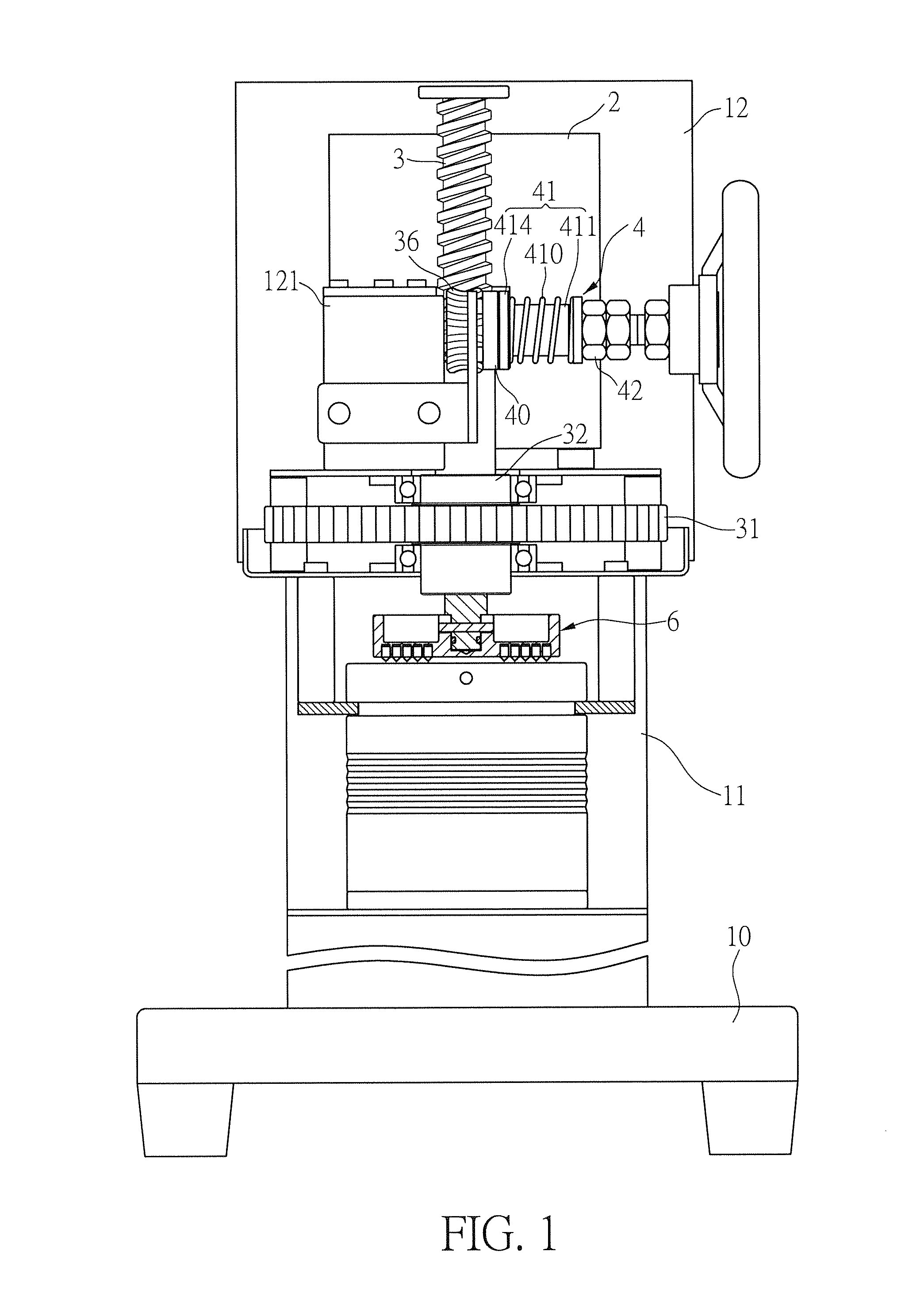
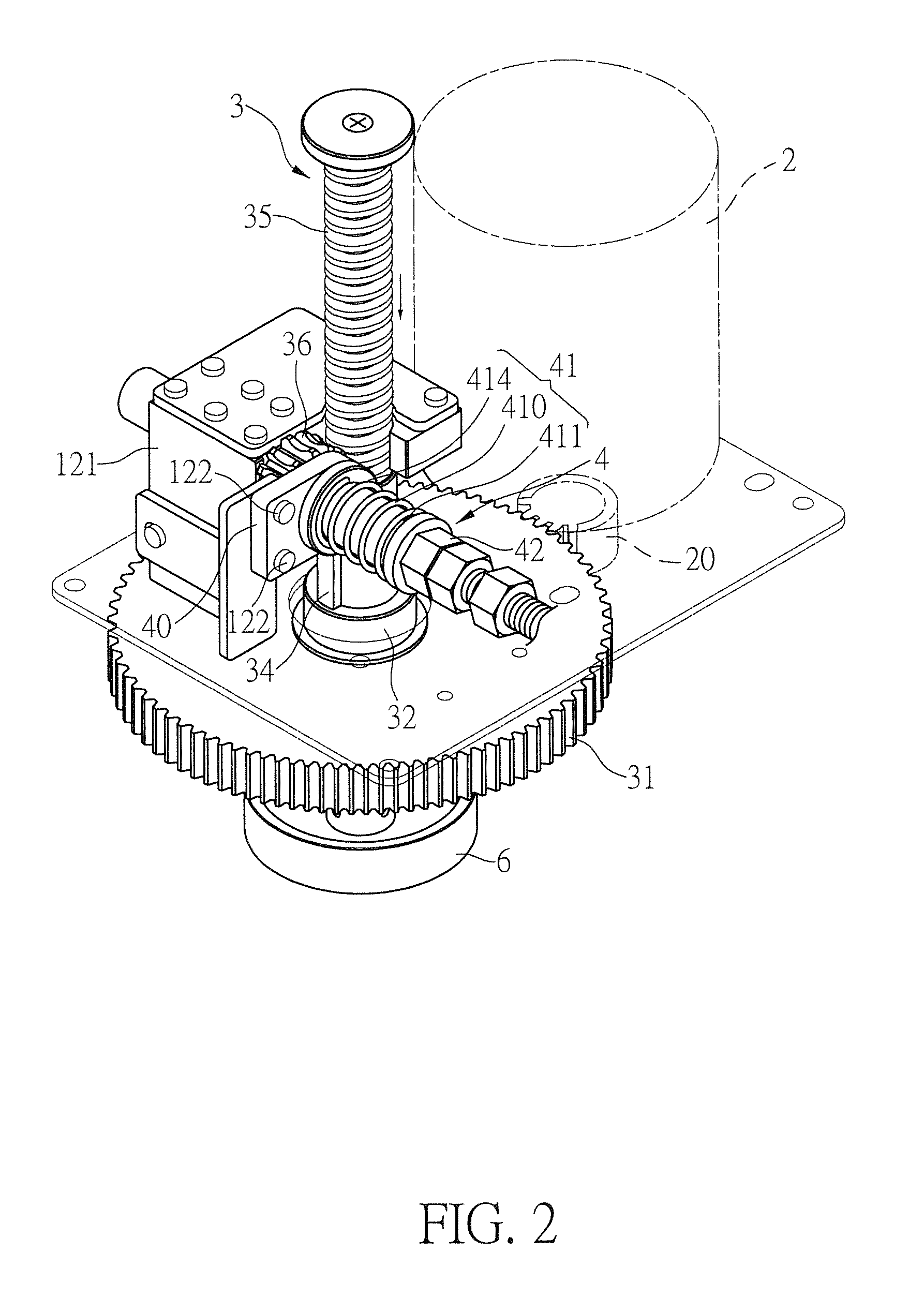
[0031]With reference to FIG. 1 for an ice shaver structure of the present invention, the ice shaver structure comprises a base 10, a pillar 11 erected from the base 10, a machine head 12 disposed at the top of the pillar 11, and the machine head 12 further comprising a transmission mechanism as shown in FIGS. 2 to 4. The transmission mechanism further comprises a driving motor 2 having a driving gear 20 installed to the driving motor, a worm shaft 3 vertically installed next to the driving motor 2 and includes an ice pressing tray 6 installed at the bottom of the worm shaft 3 for controlling an ice block, and the worm shaft 3 has a driven gear 31 engaged with the driving gear 20...


PUM


Abstract

An ice shaver structure includes a worm shaft, an ice pressing tray installed at the bottom of the worm shaft for controlling ice block, a thread section formed on the worm shaft and engaged with a worm gear, a resisting mechanism installed on the worm gear and having a stopper fixed to an ice shaver and abutted against an axial surface of the worm gear, and a resilient device abutted against the stopper. The resilient device has a position-adjusting fixing element for determining an elastic force produced by the resilient device after being compressed, and the elastic force is acted on the stopper to push the stopper to press against the worm gear, such that the resilient device becomes a relative fixed end which is difficult to turn, so that the worm shaft can be driven by a motor to produced up-and-down displacements.

Description

FIELD OF THE INVENTION[0001]The present invention relates to an ice shaver structure, in particular to the ice shaver having a worm gear with rotational resistance for driving a worm shaft to move up and down.BACKGROUND OF THE INVENTION[0002]With reference to FIGS. 1 and 3 for an ice shaver as disclosed in R.O.C. Utility Model No. 581239, the elements of this patented invention are labeled with the numerals originally used in the patent specification, and the ice shave comprises a casing 10 having a vertical worm shaft 11, and an ice pressing tray 14 coupled to the bottom of the worm shaft 11 for controlling ice block, and the worm shaft 11 is driven by a motor 20 to rotate. On the other hand, the casing 10 includes a recess with a transverse accommodating groove 15, a shaft rod 16 passing through the recess, and a worm gear 18 disposed at an end of the shaft rod 16, wherein the worm gear 18 is engaged with the worm shaft 11, and a spring S1 is sheathed on the shaft rod 16. In the t...

Claims


Application Information

Patent Timeline
IPC IPC(8): F25C5/12
CPCF25C5/12
Inventor HSU, SHIH-JUNG
Owner HSU SHIH JUNG
Why Eureka
Try Eureka