Grease gun coupler

a grease gun and coupler technology, applied in the direction of hose connection, manual lubrication, couplings, etc., can solve the problems of affecting the shape of the grease fitting is altered, and the operator needs to be careful, so as to improve the grip of the retraction device, and improve the grip

Inactive Publication Date: 2015-04-30
Y&D BROS INNOVATIONS
View PDF2 Cites 17 Cited by
  • Summary
  • Abstract
  • Description
  • Claims
  • Application Information

AI Technical Summary

Benefits of technology

[0060]In using a coupler according to the embodiments above comprising the third means for biasing, an operator again pushes the coupler against a grease fitting. The grease fitting thus inserted in the coupler pushes the piston inside the coupler (i.e. away from the grease fitting accepting end) to its engaged position. When the head of the grease fitting has passed the openings for the ball bearings, the ball bearings fall inwards and engage the neck of the grease fitting. Then, the operator pushes the outer sleeve toward its ball bearing engaging end to its first engaged position. The outer sleeve is maintained in this position (despite the bias by the third means for biasing) by the outward pressure exerted by the ball bearings. This secures the grease fitting in the coupler. With the coupler thus locked on the grease fitting, the operator may let go of it. To detach the coupler from the grease fitting, the operator simply pushes the inner sleeve towards its grease fitting accepting end so that the outer sleeve is in its disengaged position. It should be noted that this can easily be accomplished by pushing the tube of the grease gun toward the grease fitting since the inner sleeve is attached to the tube. It should also be noted that in this operation, the outer sleeve does not move. This movement is thus equivalent to retracting the outer sleeve over the inner sleeve. In any case, this releases the ball bearings, which in turn allow the first means for biasing to push the piston toward the grease fitting accepting end to its disengaged position. The piston thereby expels the grease fitting from the coupler.
[0061]This configuration comprising a pi

Problems solved by technology

Further, repeated use and general wear and tear can also alter the shape of the grease fitting.
However, such couplers wear out quickly because of the way they engage to and disengage from the grease fittings.
Another disadv

Method used


Image

  • Grease gun coupler
  • Grease gun coupler
  • Grease gun coupler

Examples


Embodiment Construction

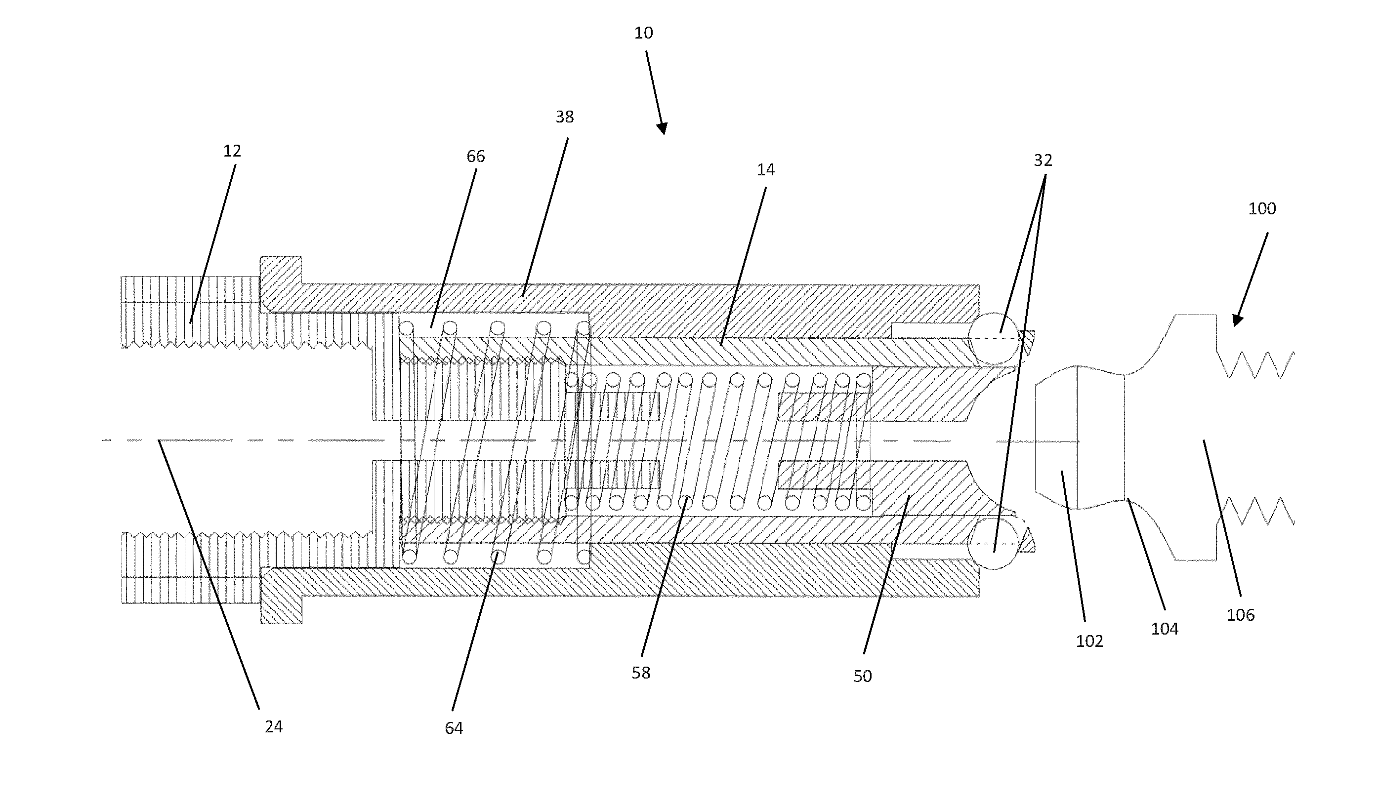
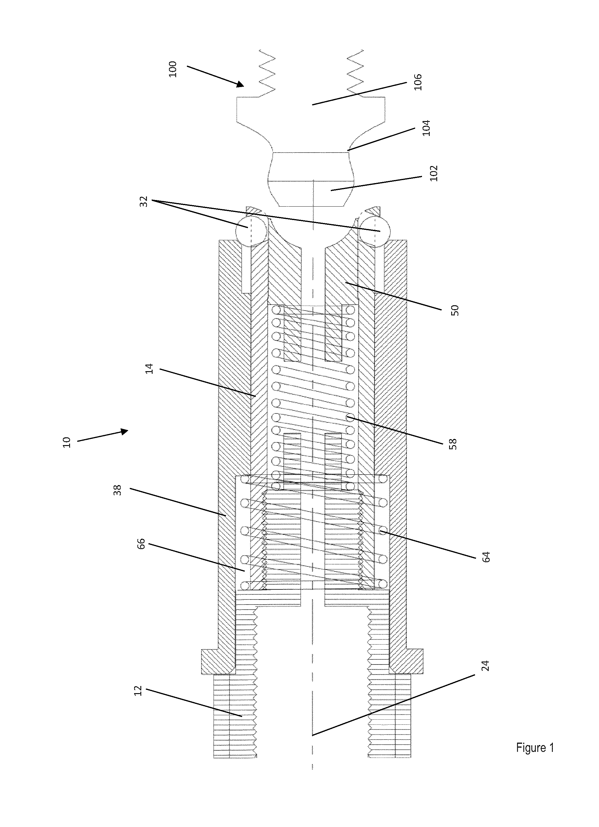
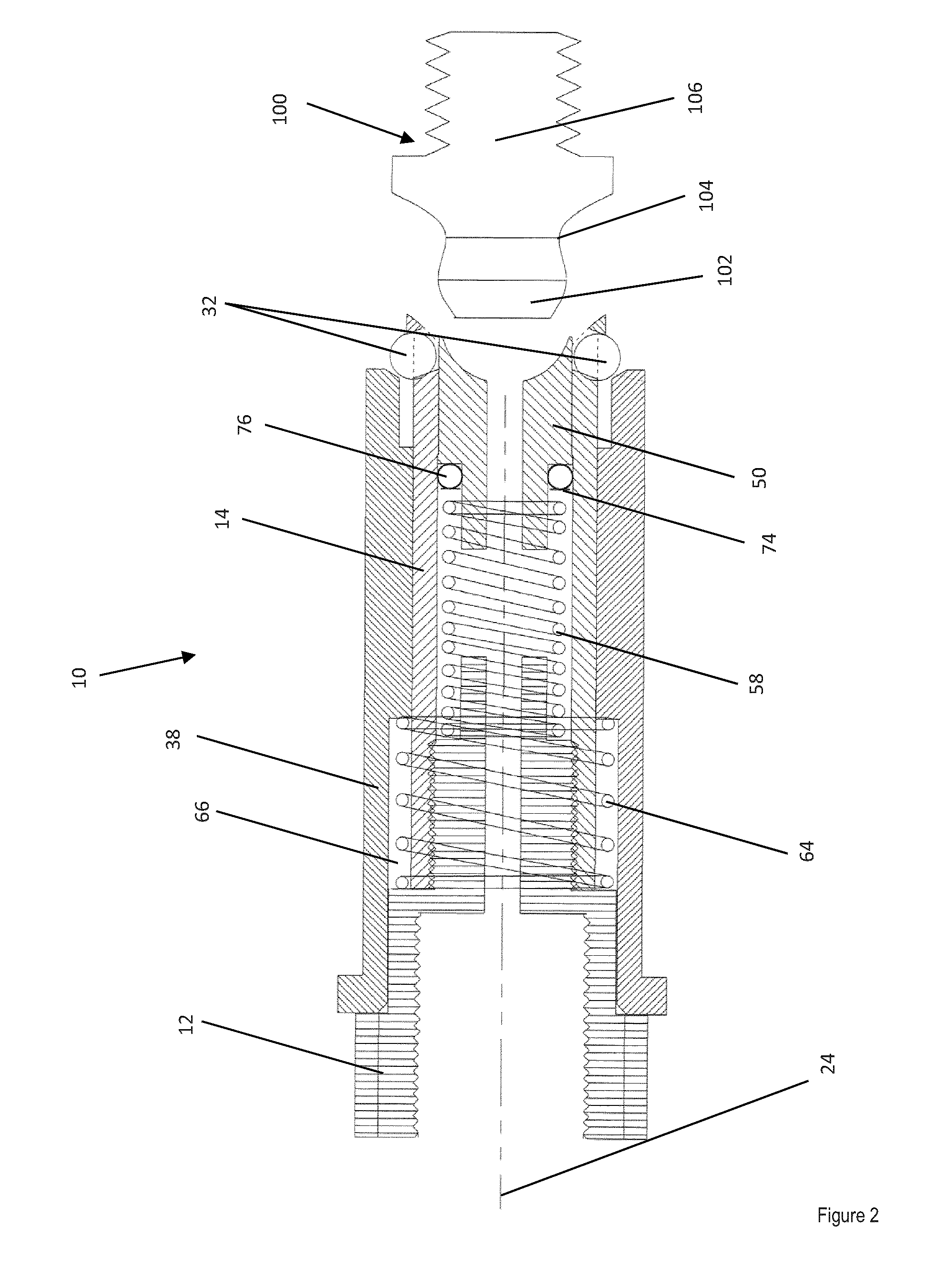
[0044]Turning now to the invention in more details, there is provided a grease gun coupler for delivering grease from a tube of a grease gun to a grease fitting.

[0045]The inventors have conducted much experimentation and went through many iterations to arrive at the couplers of the invention. Many of the difficulties encountered related to the fact that grease fittings vary in size and length. It has been a challenge to arrive at a solid coupler that (A) allows various grease fittings to penetrate far enough in the coupler and (B) allows ball bearings to penetrate sufficiently inside the coupler neck, so that the various grease fittings are properly secured.

[0046]The coupler of the invention comprises an elongated inner sleeve, which has a longitudinal axis and two ends. In use, the grease flows in the coupler along the longitudinal axis. The first end of the inner sleeve is the end to which the tube of the grease gun will attach; it can be called the tube attachment end. The second...


PUM


Abstract

A grease gun coupler for delivering grease from a tube of a grease gun to a grease fitting is provided. Insertion of a grease fitting in the coupler pushes in a piston, allows a bias or an operator to push an outer sleeve towards the grease fitting, which biases the ball bearings inwards, thus securing the grease fitting in the coupler. Retraction of the outer sleeve releases the ball bearings, thus allowing another bias to push back the piston and expel the grease fitting.

Description

CROSS REFERENCE TO RELATED APPLICATIONS[0001]This application claims benefit, under 35 U.S.C. §119(e), of U.S. provisional application Ser. No. 61 / 652,372, filed on May 29, 2012FIELD OF THE INVENTION[0002]The present invention relates to a grease gun coupler. More specifically, the present invention is concerned with a coupler that sealably secures grease fittings of various shapes and sizes.BACKGROUND OF THE INVENTION[0003]Grease guns are a common workshop and garage tool used for lubrication. The purpose of the grease gun is to apply lubricant through an aperture to a specific point, usually on a grease fitting. Channels behind the grease fitting lead to where the lubrication is needed. Grease guns can be hand-powered or air-powered (pneumatic). The grease gun can be charged or loaded with any of the various types of lubricants, but usually thick heavy grease is used.[0004]Grease fittings are also called grease nipples, Zerk fittings, and Alemite fittings. They are metal fittings ...

Claims


Application Information

Patent Timeline
IPC IPC(8): F16N21/04F16N5/02F16N3/12
CPCF16N21/04F16N5/02F16N3/12F16L37/23F16L37/407
Inventor BOUCHER, DANIELBOUCHER, YVES
Owner Y&D BROS INNOVATIONS
Why Eureka
Try Eureka