Eureka AIR delivers breakthrough ideas for toughest innovation challenges, trusted by R&D personnel around the world.

Inflatable surfing apparatus and method

a technology of inflatable surfing and apparatus, applied in the field of inflatable surfing apparatus and method, can solve the problems of unfavorable permanent installation of surfing simulators at those locations, uncomfortable contact with riders, and lack of surfing experien

Active Publication Date: 2015-04-30
WHITEWATER WEST INDS
View PDF2 Cites 14 Cited by
  • Summary
  • Abstract
  • Description
  • Claims
  • Application Information

AI Technical Summary

Benefits of technology

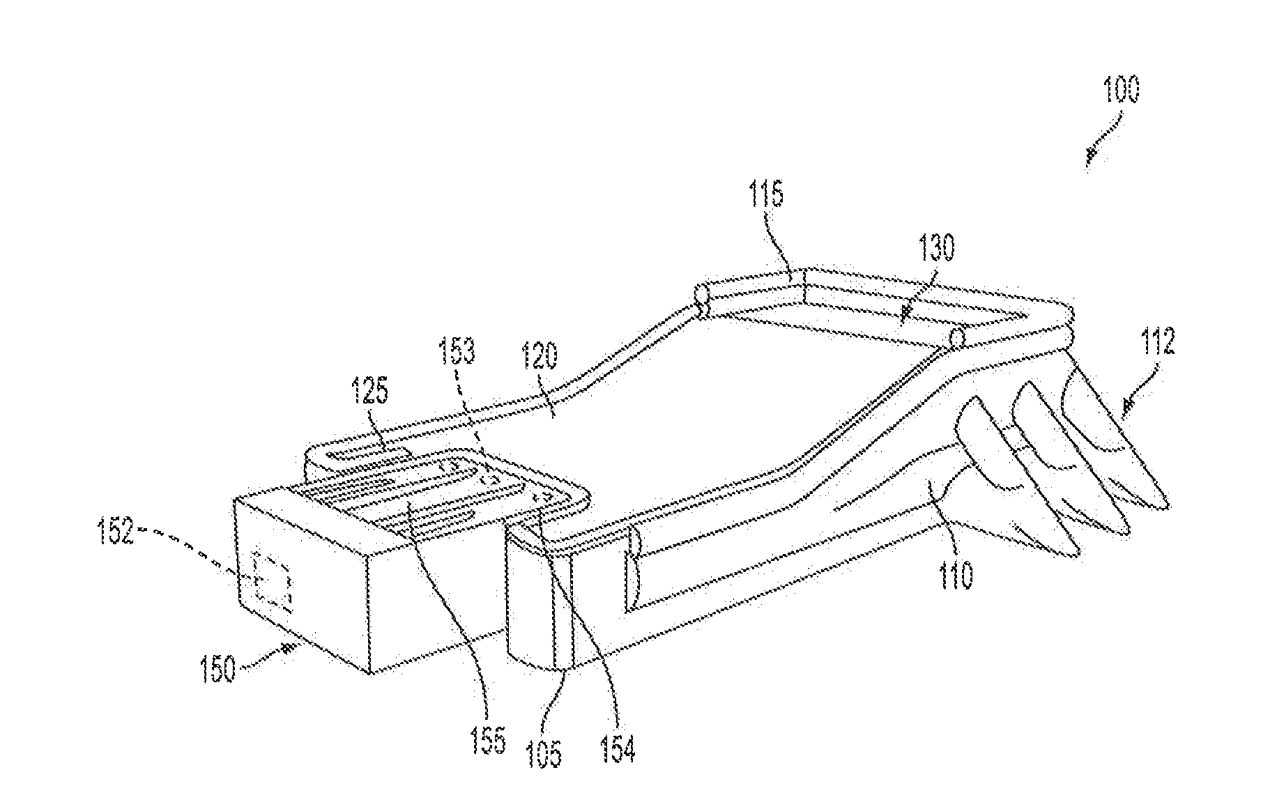
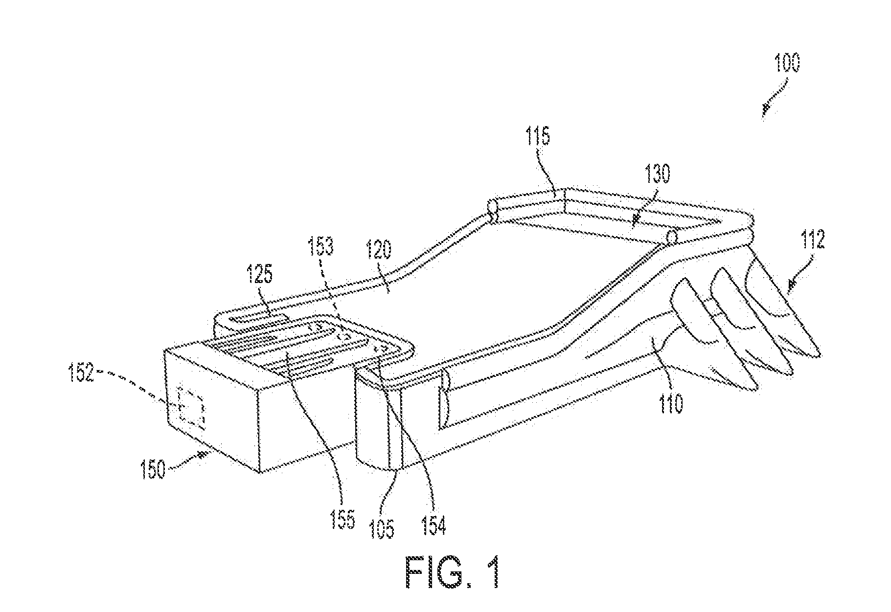
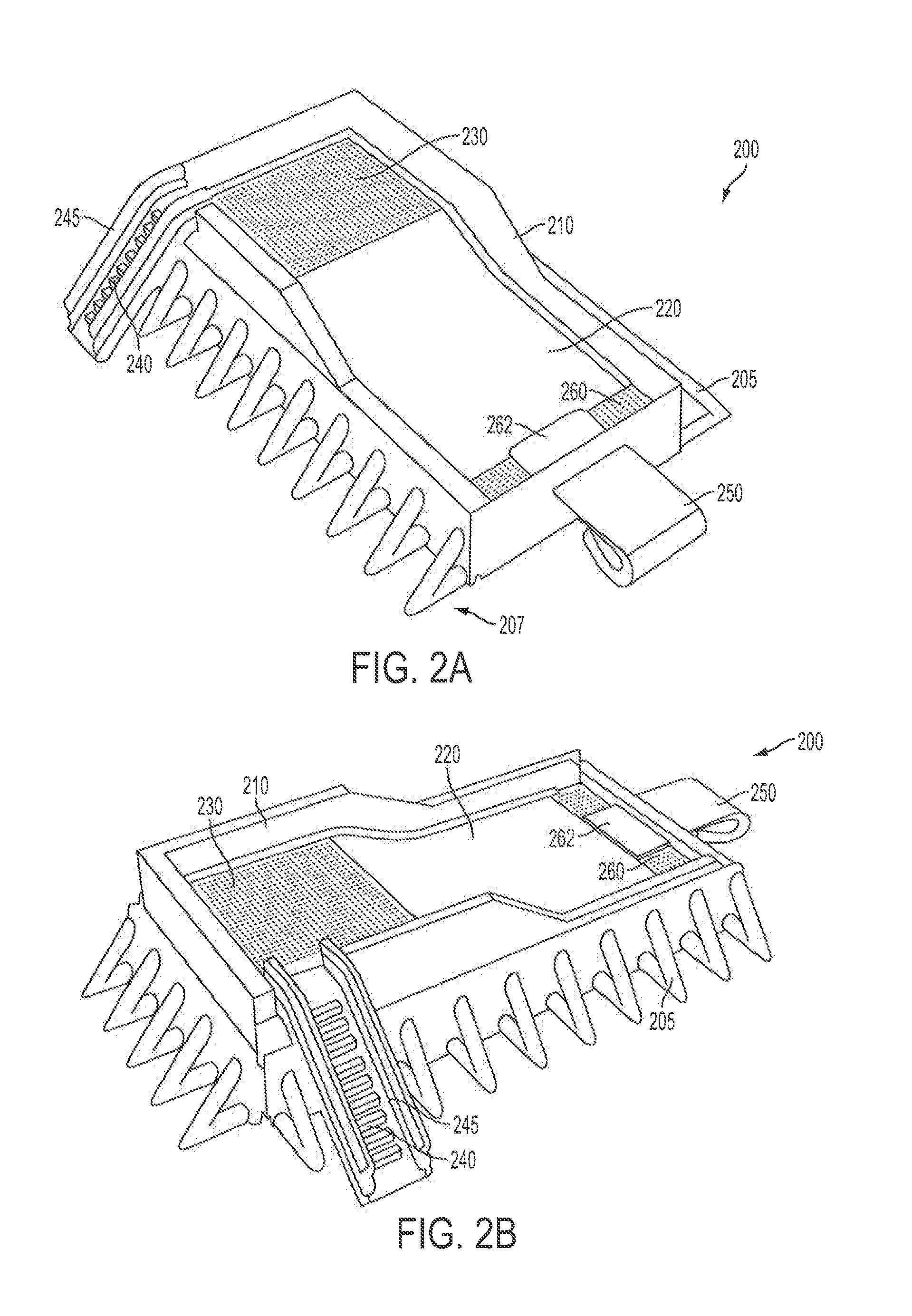
The patent describes a water attraction with a base that has an inflatable portion and a riding surface that floats on a volume of fluid inside the base. This allows for a unique experience of riding on air or water. The patent also includes a method for assembling the water attraction by inflating the base and adding water to the inflated base to create a cavity where the riding surface floats on top of the water. Overall, the patent describes a new way to create water-based amusement experiences.

Problems solved by technology

However, users without much surfing experience, either in the ocean or upon surfing machines, commonly fall off of the board during initial attempts at using the surfing machine and the surfaces of these apparatuses can make uncomfortable contact with a rider upon the rider's falling off of their board.
Unfortunately, given the relatively short duration that many competitions extend, some lasting only a few days in duration, permanent installation of surfing simulators at those locations is not feasible.
While some mobile surfing simulators have been developed, the comparably long and typically complex assembly and / or disassembly procedures, oftentimes taking greater time than the entire duration of the event itself, makes such devices undesirable to many potential event holders or organizers.
These conventional simulators commonly utilize a large number of component parts that require vast numbers of shipment containers for their assembly, adding significantly to the cost associated with transporting and assembling the simulators at a desired geographic location.

Method used


Image

  • Inflatable surfing apparatus and method
  • Inflatable surfing apparatus and method
  • Inflatable surfing apparatus and method

Examples


Embodiment Construction

[0029]The detailed description of exemplary embodiments herein makes reference to the accompanying drawings and pictures, which show the exemplary embodiments by way of illustration and its best mode. While these exemplary embodiments are described in sufficient detail to enable those skilled in the art to practice the invention, it should be understood that other embodiments may be realized and that logical and mechanical changes may be made without departing from the spirit and scope of the invention. Thus, the detailed description herein is presented for purposes of illustration only and not of limitation. For example, the steps recited in any of the method or process descriptions may be executed in any order and are not limited to the order presented. Moreover, any of the functions or steps may be outsourced to or performed by one or more third parties. Furthermore, any reference to singular includes plural embodiments, and any reference to more than one component may include a ...


PUM

PropertyMeasurementUnit
Thicknessaaaaaaaaaa
Flow rateaaaaaaaaaa
Volumeaaaaaaaaaa

Abstract

A water or other amusement attraction that includes an inflatable portion or material. A cavity of the attraction is located underneath an upper surface, the upper surface configured to support a flow of water and at least one rider thereon. A volume of water is configured to be disposed within the cavity, the upper surface floating upon the volume of water while connected to at least one side wall, floor, and / or nozzle structure. A pump and nozzle assembly, positioned outside of the cavity, communicates with the water within the cavity for flowing a portion of the water over the upper surface. A drainage portion, adjacent to the upper surface, drains the flowing water back into the cavity for recirculation. Support components, such as a plurality of beams or an inflatable grid structure help maintain stability for the attraction.

Description

CROSS REFERENCE TO RELATED APPLICATIONS[0001]This application claims the benefit of U.S. Provisional Patent Application Ser. No. 61 / 897,696, filed on Oct. 30, 2013, entitled “INFLATABLE SURFING APPARATUS AND METHOD,” which is hereby incorporated by reference in its entirety.BACKGROUND[0002]1. Field[0003]The present invention relates generally to amusement attractions, such as surfing simulators or other wave machines. More particularly, the present invention relates to mobile or permanently installed water or surfing attractions that incorporate one or more inflatable sections or areas.[0004]2. Description of the Related Art[0005]Water attractions (e.g., waterslides, surfing slides or machines, boogie-boarding slides, etc.) are a popular entertainment activity during periods of warm weather. Conventional water attractions are commonly made of fiberglass or other rigid or semi-rigid materials that provide a smooth and slippery surface for supporting a flow of water thereon to transpo...

Claims


Application Information

Patent Timeline
IPC IPC(8): A63G31/00B63B35/73B63B35/79
CPCA63G31/007B63B35/73B63B35/79A63G21/18B63B34/70
Inventor VICENTE, ORIOL
Owner WHITEWATER WEST INDS
Why Eureka
Eureka Blog
Learn More