Remote operation of a bedding climate control apparatus

a technology of climate control and remote operation, which is applied in the field of home appliances, can solve the problems of no means to cool the user, no fresh air flowing into the bedding, and devices that are limited in wattage capacity, so as to efficiently deliver the needed airflow, dampen the sound generation, and reduce the effect of nois

Inactive Publication Date: 2015-05-07
ARAMLI MARK
View PDF27 Cites 16 Cited by
  • Summary
  • Abstract
  • Description
  • Claims
  • Application Information

AI Technical Summary

Benefits of technology

The patent text describes a device that reduces the noise generated by a fan/blower. The device includes a housing that is oversize to accommodate acoustic foam at the air intake to dampen the sound. The fan/blower is run at quieter speeds to keep the pressure drop low. The device also includes an oversize ceramic thermal element that can heat more air at a time to achieve a lower temperature, which prevents dust and lint from burning. The air duct is oversize to reduce pressure drop and allow the fan/blower to operate at a lower speed. The technical effects of the device include reduced noise, improved efficiency, and improved safety.

Problems solved by technology

The technical problem addressed in this patent text is the need for a more efficient and safe way to control the temperature of bedding and sheets. Current options like electric blankets and mattress pads are limited in their wattage and typically take a long time to heat or cool the bed. There is also no circulation of fresh air and some products can only be used with special gowns. The invention aims to provide a bedside remote control that can deliver more dry heating power to bedding and sheets, while also being safe and quiet.

Method used


Image

  • Remote operation of a bedding climate control apparatus
  • Remote operation of a bedding climate control apparatus
  • Remote operation of a bedding climate control apparatus

Examples


Embodiment Construction

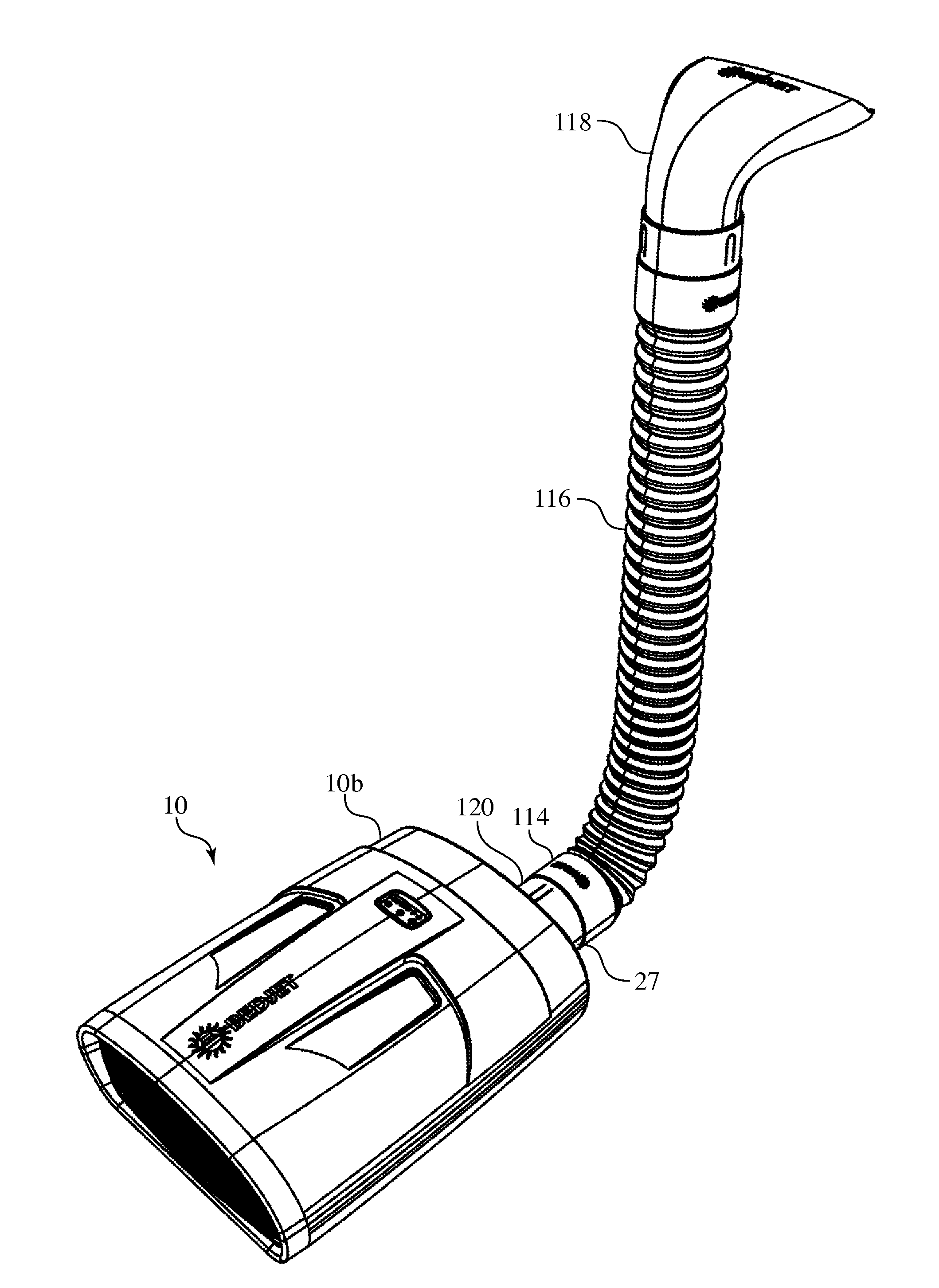
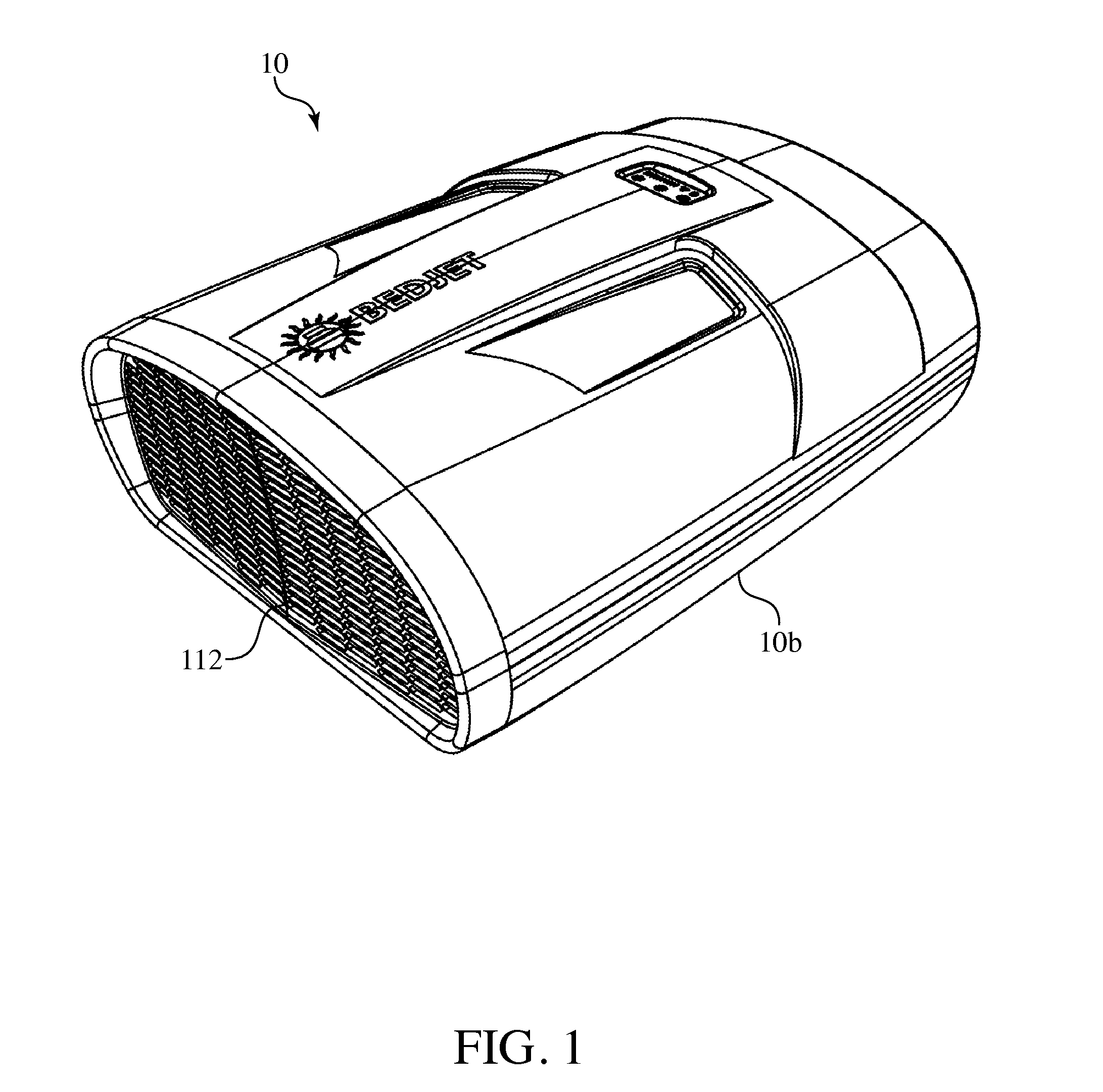
[0052]Turning to the drawing, FIG. 1 shows a bedding climate control apparatus 10 is shown in accordance with the invention. The bedding climate control apparatus 10 has housing 106 that contains a fan or blower (not shown in FIG. 1) that receives air via air intake grille 112. The air may be tempered or heated with a thermal element (not shown in FIG. 1) that is contained within the housing 106 in the discharge side of the fan or blower. The structure of the housing 106 corresponds to that depicted in US design patent application Ser. No. 29 / 501,656, whose contents are incorporated herein by reference.

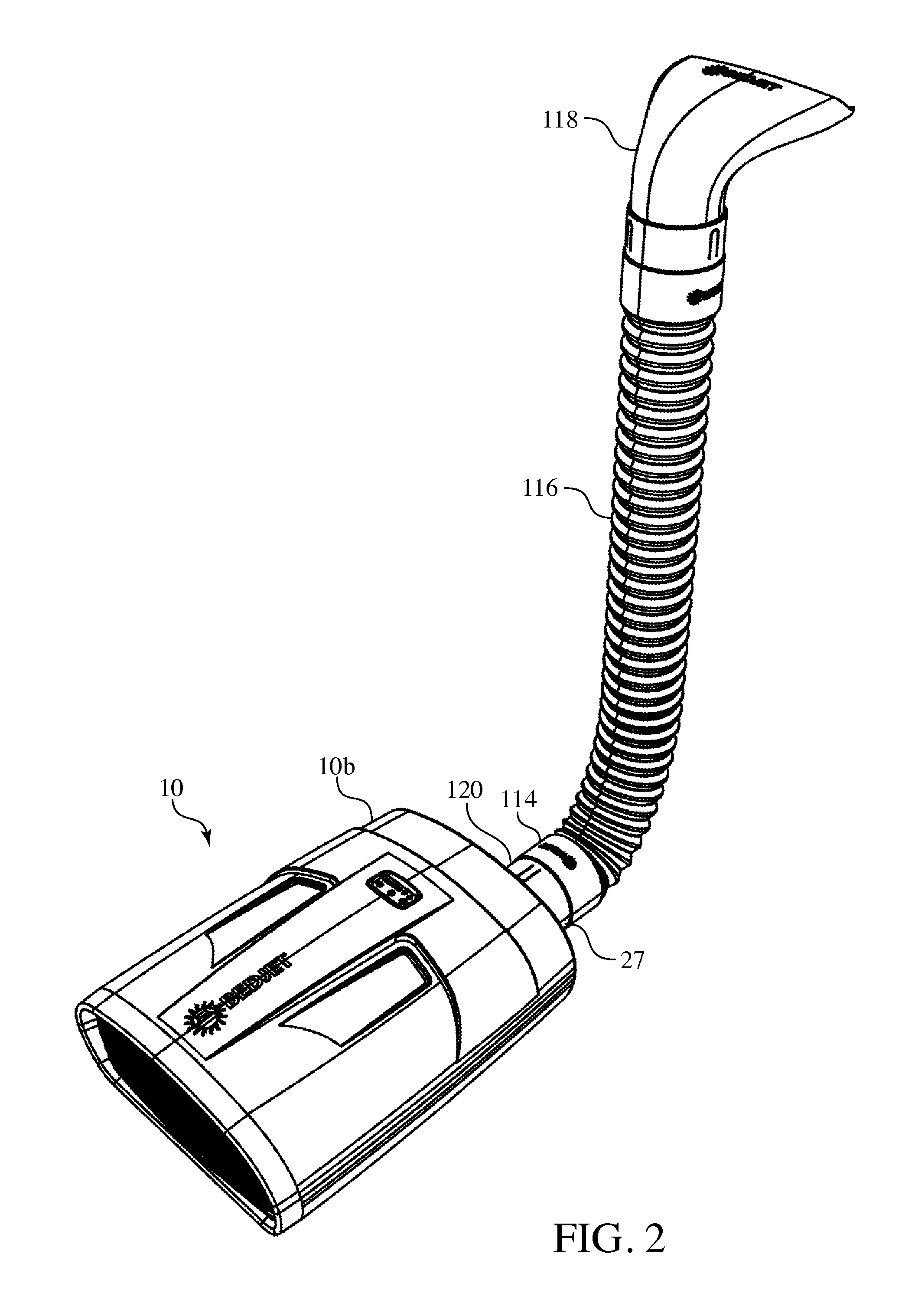
[0053]FIG. 2 shows the bedding climate control apparatus 10 of FIG. 1. Air enters through the intake grille 112 and exits through the cylindrical discharge outlet 120. An end 114 of a hose 116 is mechanically coupled to the cylindrical outlet 120 of the bedding climate control apparatus 10 via any conventional mechanical coupler 27, such as engaging screw threads (not shown). The hose...


PUM


Abstract

A bedding climate control apparatus that delivers, in a quiet manner, forced airflow from a fan/blower within a housing to selectively deliver tempered (heated via a thermal element) and untempered (room temperature) air through a flexible hose to bedding. The quiet manner is attained with acoustic foam in the path of incoming airflow to the fan/blower and by oversizing each of the components that create a pressure drop including the capacity of the fan/blower over what is needed to deliver a required amount of airflow. Temperature may be set remotely via a wireless remote control and via a protocol access enabled device.

Description


Claims


Application Information

Patent Timeline
Owner ARAMLI MARK
Why Eureka
Try Eureka