
Accelerometer with Offset Compensation

a technology of offset compensation and accelerometer, which is applied in the direction of speed/acceleration/shock measurement, speed/acceleration/shock measurement, testing/calibration of speed/acceleration/shock measurement devices, etc., which can solve problems such as two surfaces, output data representing the property being measured (e.g. acceleration) to be erroneous

Active Publication Date: 2015-05-07
ANALOG DEVICES INC
View PDF6 Cites 11 Cited by
  • Summary
  • Abstract
  • Description
  • Claims
  • Application Information

AI Technical Summary

Benefits of technology

The patent describes a device that detects movement in a device by using a combination of stress and acceleration capacitors. The device has a stationary finger and a movable finger that moves above the substrate. The device also has multiple acceleration capacitors with both movable and stationary fingers, and multiple variable stress capacitors with at least one stationary finger. A frame may also be suspended above the substrate to help detect movement. The technical effect of this invention is that it provides a more accurate way to detect movement in a device, which can be useful in various applications such as sensing and control.

Problems solved by technology

Problems can arise, however, when the temperatures of the two surfaces change.
Substrate bending or flexing consequently can affect movement of the die structures, thus causing the output data representing the property being measured (e.g., acceleration) to be erroneous.
In a similar manner, mechanically induced linear or torsional stress applied to the package also can be translated to the die, thus causing the same undesirable effects.

Method used


Image

  • Accelerometer with Offset Compensation
  • Accelerometer with Offset Compensation
  • Accelerometer with Offset Compensation

Examples


Embodiment Construction

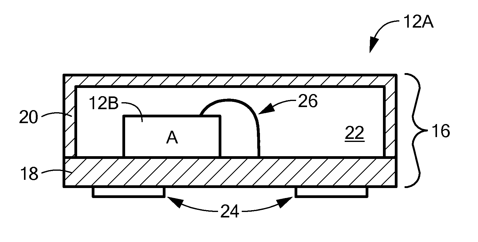
[0005]In accordance with one embodiment of the invention, an accelerometer has a movable mass suspended above a substrate, and a variable acceleration capacitor supported by the substrate. The accelerometer also has a mass anchor securing the mass to the substrate, while the acceleration capacitor has both a stationary finger extending from the substrate, and a movable finger extending from the movable mass. The accelerometer also has a variable stress capacitor, which also includes the stress finger, for determining movement of the mass anchor relative to the acceleration capacitor stationary finger or substrate.

[0006]In some embodiments, such as those similar to that noted above, the acceleration capacitor has at least two fingers—one affixed to the movable mass and the other to the substrate via an anchor. The variable stress capacitor also has two fingers that each are affixed to the substrate in a manner similar to the other elements—one is affixed to the substrate in a manner ...


PUM


Abstract

An accelerometer has a movable mass suspended above a substrate, and a variable acceleration capacitor supported by the substrate. The movable mass has a mass anchor securing the mass to the substrate, while the acceleration capacitor has both a stationary finger extending from the substrate, and a movable finger extending from the movable mass. The accelerometer also has a variable stress capacitor, which also includes the stress finger, for determining movement of the mass anchor relative to the substrate.

Description

FIELD OF THE INVENTION[0001]The invention generally relates to accelerometers and, more particularly, the invention relates to mitigating stress induced errors in accelerometers.BACKGROUND OF THE INVENTION[0002]Microelectromechanical systems (“MEMS”) are used in a growing number of applications. For example, MEMS currently are implemented as gyroscopes to detect pitch angles of airplanes, and as accelerometers to selectively deploy air bags in automobiles. In simplified terms, such MEMS devices typically have a structure suspended above a substrate, and associated on-chip or off-chip electronics that both senses movement of the suspended structure and delivers the sensed movement data to one or more external devices (e.g., an external computer). The external device processes the sensed data to calculate the property being measured (e.g., pitch angle or acceleration).[0003]The associated electronics, substrate, and movable structure typically are formed on one or more dies (referred ...

Claims


Application Information

Patent Timeline
Patent Type & Authority Applications(United States)
IPC IPC(8): G01P15/125
CPCG01P15/125G01P21/00G01P2015/0814G01P2015/0868
Inventor CLARK, WILLIAM A.
Owner ANALOG DEVICES INC
Learn More