Navigation System with Monocentric Lens and Curved Focal Plane Sensor

a technology of focal plane sensor and navigation system, which is applied in the field of optical navigation system, can solve the problems of limited number of navigational stars that may be used, required precision, and substantial problems

Active Publication Date: 2015-05-07
CHARLES STARK DRAPER LABORATORY
View PDF7 Cites 22 Cited by
  • Summary
  • Abstract
  • Description
  • Claims
  • Application Information

AI Technical Summary

Benefits of technology

[0052]The camera may be automatically caused to capture an image. A portion, less than all, of the image may be automatically analyzed. The portion of the image that is analyzed corresponds to the portion of the camera field of view exposed to the scene.
[0053]The camera may include a plurality of image sensor arrays. Each image sensor array of the plurality of image sensor arrays may include a plurality of pixels. The method may further include reading a subset, less than all, of the pixels of the plurality of image sensor arrays. The subset may correspond to the selectable portion of the camera field of view exposed to the scene.
[0054]Yet another embodiment of the present invention provides a computer program product for exposing a selectable portion, less than all, of a field of view of a camera to a scene. A baffle assembly is disposed adjacent the camera. The camera is aimed toward an interior of the baffle assembly. The baffle assembly is configured to define an aperture whose position on the baffle assembly is electronically adjustable. The aperture defines the selectable portion, less than all, of the field of view of the camera exposed to the scene. The computer program product includes a non-transitory computer-readable medium. Computer readable program code is stored on the medium. The computer readable program code is configured to cause the processor to perform an operation, including adjusting the position of the aperture on the baffle assembly, such that the aperture is oriented toward the scene.

Problems solved by technology

However, the fixed view angle of a strapped-down star tracker limits the number of navigational stars that may be used.
However, aiming a prior art star tracker, relative to its vehicle, with the required precision poses substantial problems.
In either case, preventing stray light, such as from the sun or reflected from the moon, reaching the photocell or sensor array is challenging, particularly when a navigational star of interest is apparently close to one of these very bright objects.

Method used


Image

  • Navigation System with Monocentric Lens and Curved Focal Plane Sensor
  • Navigation System with Monocentric Lens and Curved Focal Plane Sensor
  • Navigation System with Monocentric Lens and Curved Focal Plane Sensor

Examples


Embodiment Construction

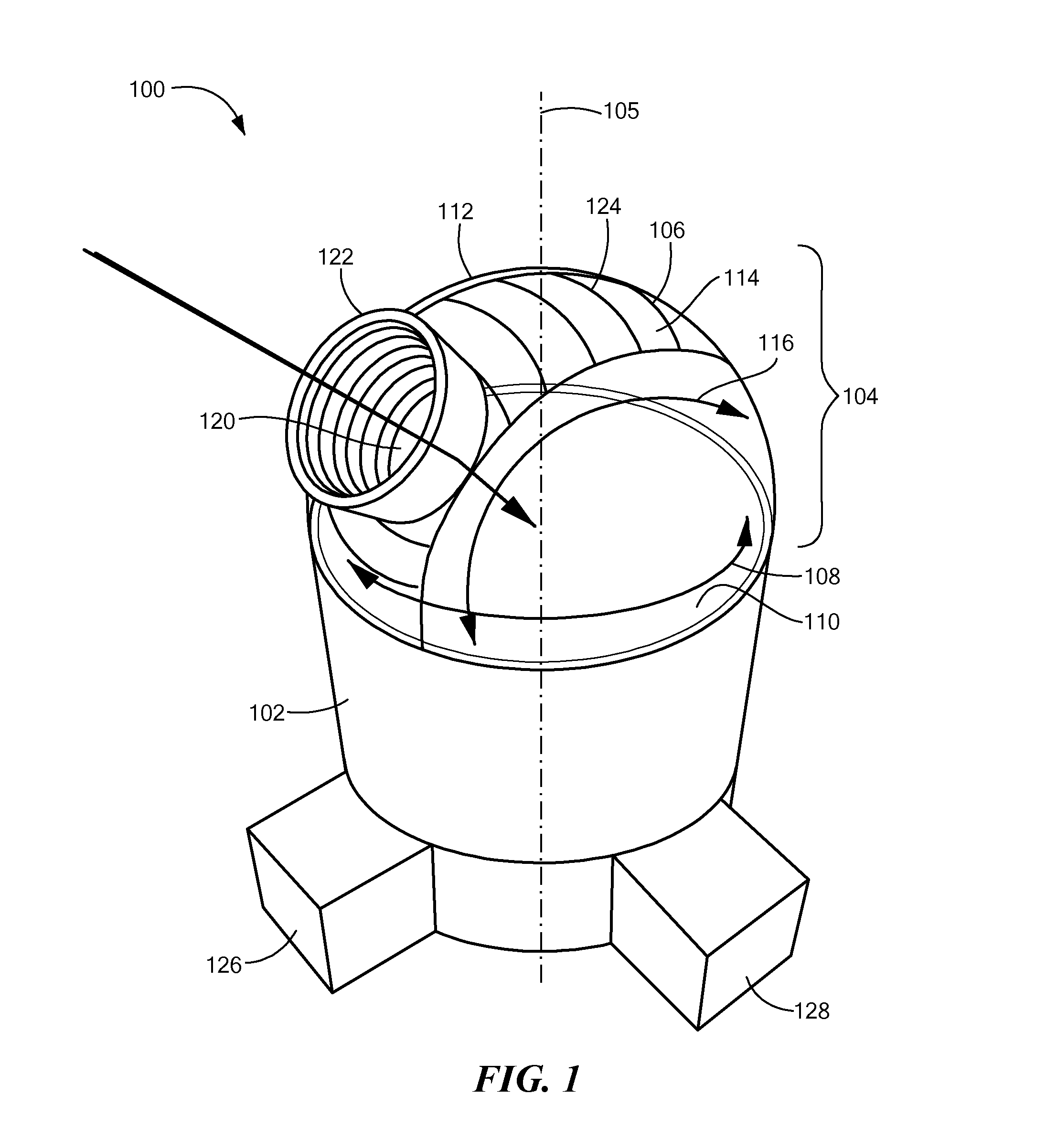
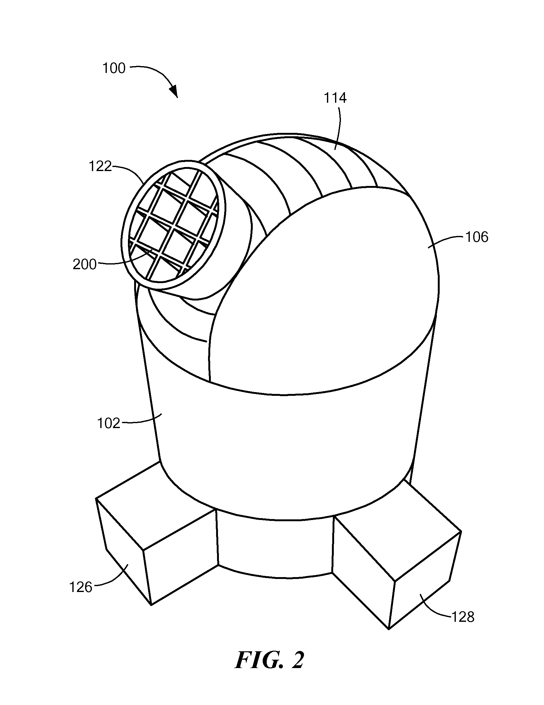
[0007]An embodiment of the present invention provides a navigation system. The navigation system includes a monocentric objective lens and a first curved image sensor array. The first curved image sensor array is disposed parallel to, and spaced apart from, the lens. The curved image sensor array includes a plurality of light-sensitive pixels on a surface of the sensor array. The surface of the sensor array having the light-sensitive pixels faces toward the lens.

[0008]The lens may have a focal length. The first image sensor array may be spaced apart from the lens by about the focal length. Thus, each of the pixels on the sensor array may be spaced apart from the lens by about the focal length.

[0009]The lens may have a field of view. The first image sensor array may be sized to receive light from less than the entire field of view of the lens. In some embodiments, the first image sensor array may be sized to receive light from less than about 80% of the field of view. In some embodim...


PUM


Abstract

A navigation system includes a monocentric lens and one or more curved image sensor arrays disposed parallel and spaced apart from the lens to capture respective portions, not all, of the field of view of the lens.

Description

CROSS REFERENCE TO RELATED APPLICATIONS[0001]This application is a continuation-in-part of U.S. patent application Ser. No. 13 / 893,987, filed May 14, 2013, the entire contents of which are hereby incorporated by reference herein, for all purposes.TECHNICAL FIELD[0002]The present invention relates to optical navigation systems and, more particularly, to optical navigation systems that include monocentric lenses and curved image sensor arrays.BACKGROUND ART[0003]Most artificial satellites, spacecraft and other propelled devices such as aircraft, ship and ground vehicles (collectively referred to herein as vehicles) require information about their locations and / or attitudes to accomplish their missions. This information may be obtained from one or more sources, such as the global positioning system (GPS), ground-based radar tracking stations and / or an on-board star tracker.[0004]A star tracker is an optical device that measures bearing(s) to one or more stars, as viewed from a vehicle....

Claims


Application Information

Patent Timeline
Patent Type & Authority Applications(United States)
IPC IPC(8): H04N5/225
CPCH04N5/2259H04N23/55H04N23/58H04N23/60H04N23/45H04N23/54B64C39/024B64D47/08F41G7/007F41G7/2253G01C21/025
Inventor DAWSON, ROBIN MARK ADRIANLAINE, JUHA-PEKKA J.CHAPARALA, MURALI V.ARANT, CHARLESJAMULA, MATTHEW T.
Owner CHARLES STARK DRAPER LABORATORY
Why Eureka
Try Eureka