
Light diffusing fibers with integrated mode shaping lenses

a technology of light diffusing fibers and mode shaping lenses, applied in the field of light diffusing optical fibers, can solve the problems that optical fibers are not considered to be well-suited for use in forming extended illumination sources, and achieve good optical properties

Active Publication Date: 2015-05-07
CORNING INC
View PDF2 Cites 28 Cited by
  • Summary
  • Abstract
  • Description
  • Claims
  • Application Information

AI Technical Summary

Benefits of technology

The patent describes a method to make a fiber with a lens at one end. The fiber has tiny structures inside it that scatter light and make the fiber look like it is glowing. These structures are sealed off at the end where the lens is located, so they don't affect the optical properties of the fiber. The lens can be permanently formed or attached to the fiber, and the empty spaces where the structures were located are protected from debris. This technology allows for the creation of light-diffusing fibers with high-quality optical properties.

Problems solved by technology

Because optical fibers are typically designed to efficiently deliver light from one end of the fiber to the other end of the fiber over long distances, very little light escapes from the sides of the typical fiber, and, therefore optical fibers are not considered to be well-suited for use in forming an extended illumination source.

Method used


Image

  • Light diffusing fibers with integrated mode shaping lenses
  • Light diffusing fibers with integrated mode shaping lenses
  • Light diffusing fibers with integrated mode shaping lenses

Examples


Embodiment Construction

[0025]Reference is now made in detail to the present preferred embodiments of the disclosure, examples of which are illustrated in the accompanying drawings. Whenever possible, like or similar reference numerals are used throughout the drawings to refer to like or similar parts. It should be understood that the embodiments disclosed herein are merely examples, each incorporating certain benefits of the present disclosure.

[0026]Various modifications and alterations may be made to the following examples within the scope of the present disclosure, and aspects of the different examples may be mixed in different ways to achieve yet further examples. Accordingly, the true scope of the disclosure is to be understood from the entirety of the present disclosure, in view of but not limited to the embodiments described herein.

DEFINITIONS

[0027]Terms such as “horizontal,”“vertical,”“front,”“back,” etc., and the use of Cartesian Coordinates are for the sake of reference in the drawings and for ea...


PUM


Abstract

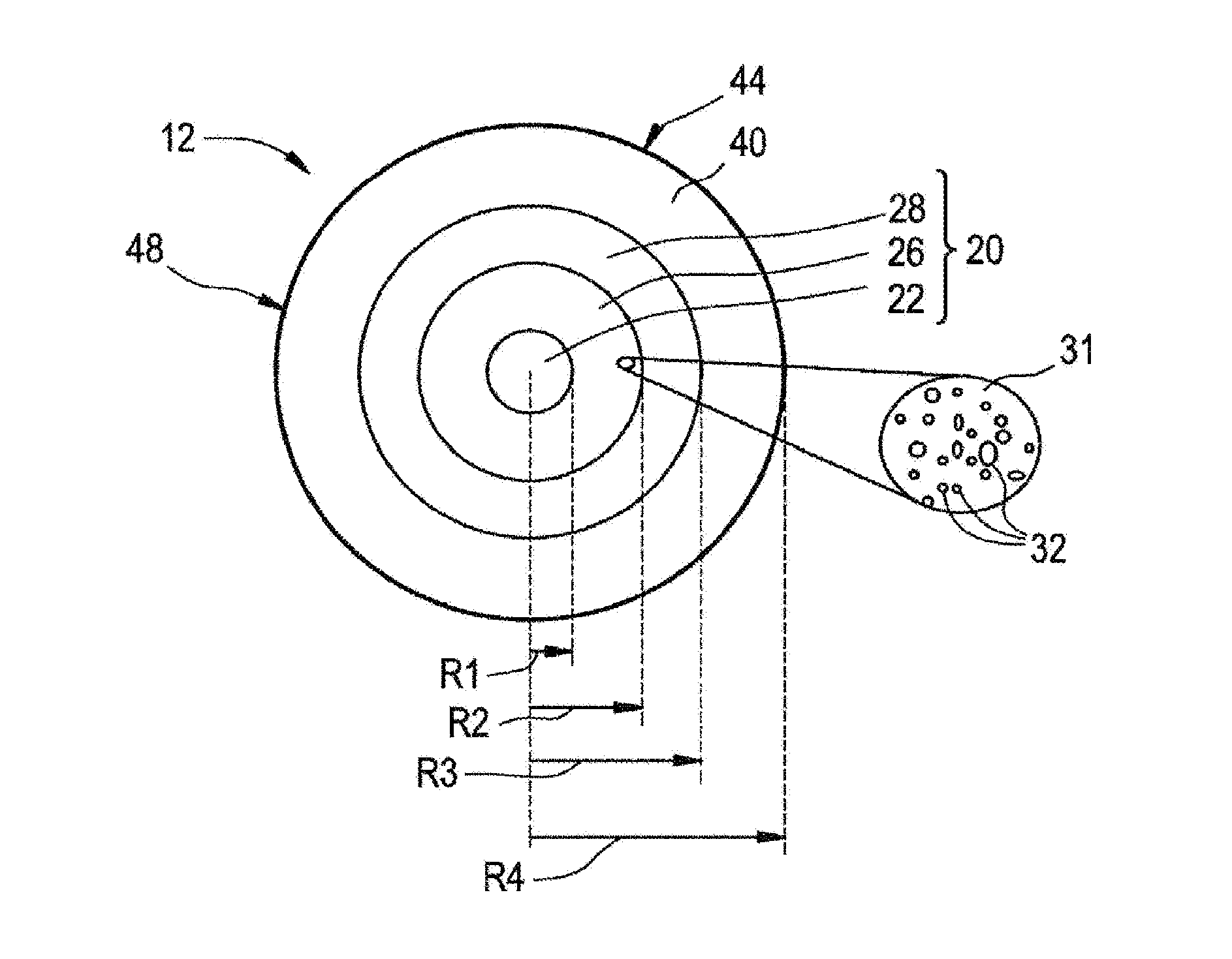
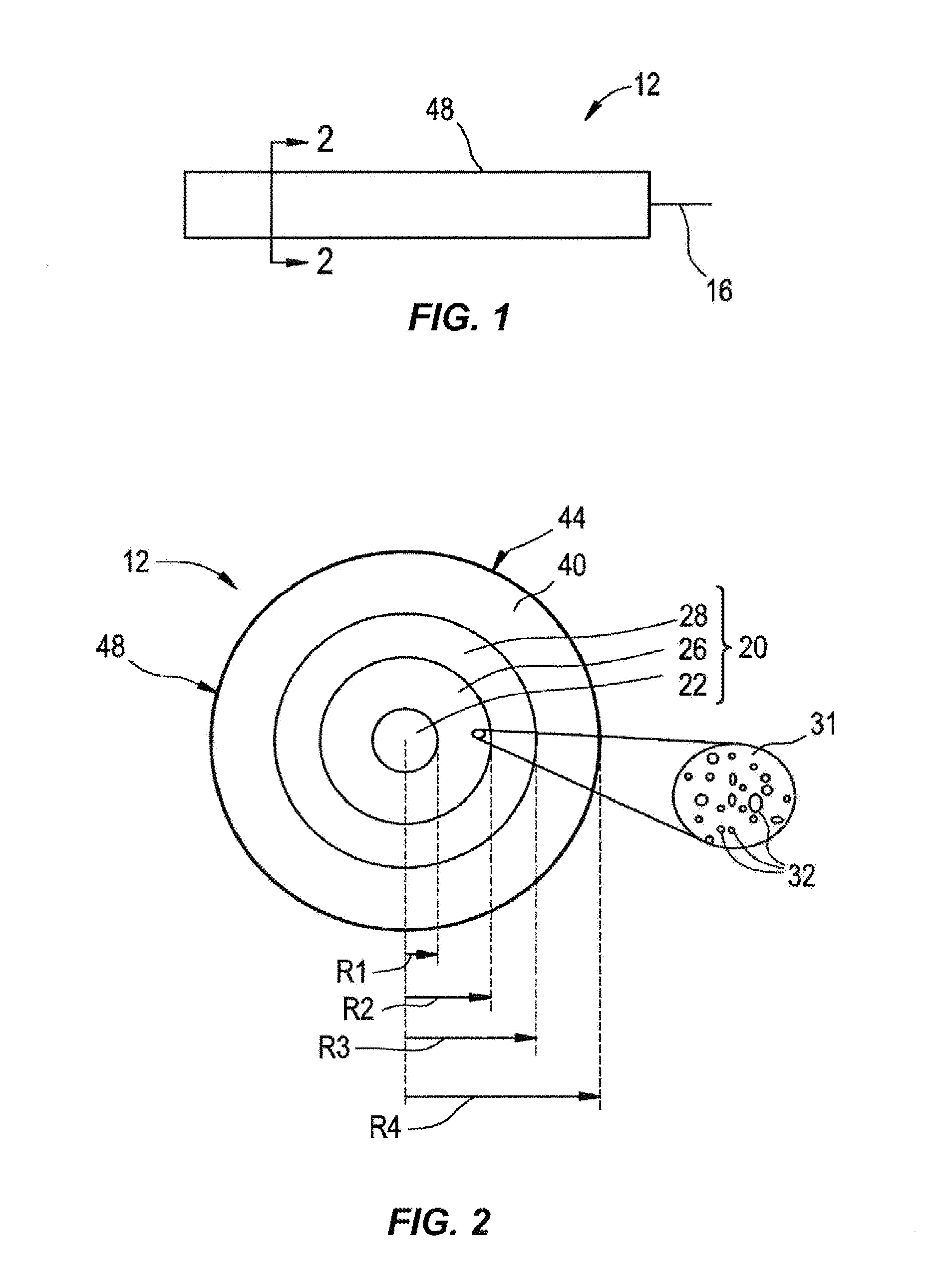
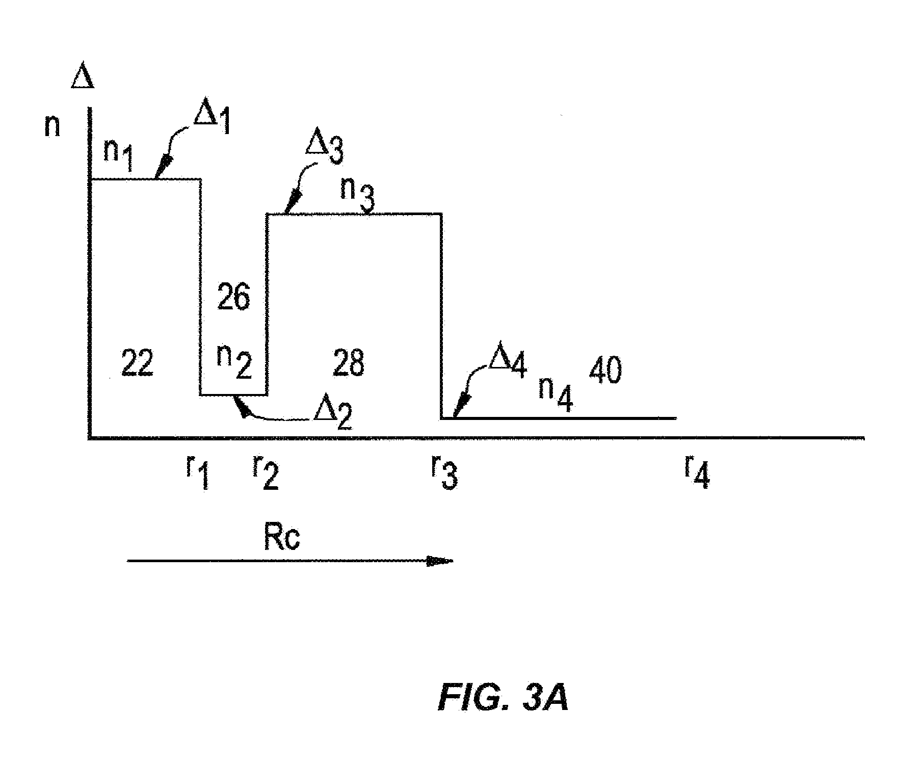
A method including the steps of providing a light-diffusing optical fiber (12a) having a glass core (20), a cladding (40) surrounding the core (20), and a plurality of nano-sized structures in the form of voids (32) situated within said core (20) or at a core-cladding boundary; cleaving the light-diffusing fiber (12a), thereby forming a cleaved end face (66); and applying energy to one or more of 1) the cleaved end face (66) and 2) the light-diffusing fiber (12b) along a portion of the length thereof adjacent the cleaved end face (66), the amount of energy being sufficient to collapse and seal the voids (32) exposed at the cleaved end face (66), leaving a sealed cleaved end face (68). A lens may then be attached to the sealed cleaved end face (68), or the sealed cleaved end face (68) may be softened sufficiently to induce formation of a lensing surface such as a convex lensing surface (60) on the sealed end face (68).

Description

[0001]This application claims the benefit of priority under 35 U.S.C. §119 of U.S. Provisional Application Ser. No. 61 / 664,349 filed on Jun. 26, 2012 the content of which is relied upon and incorporated herein by reference in its entirety.FIELD[0002]The present disclosure relates generally to light-diffusing optical fibers having a region with nano-sized structures, and in particular to light-diffusing optical fibers having a region with nano-sized structures equipped with integral or integrated lenses.TECHNICAL BACKGROUND[0003]Optical fibers are used for a variety of applications where light needs to be delivered from a light source to a remote location. Optical telecommunication systems, for example, rely on a network of optical fibers to transmit light from a service provider to system end-users.[0004]Telecommunication optical fibers are designed to operate at near-infrared wavelengths in the range from 800 nm to 1675 nm where there are only relatively low levels of attenuation d...

Claims


Application Information

Patent Timeline
Patent Type & Authority Applications(United States)
IPC IPC(8): G02B6/32G02B6/02G02B6/25
CPCG02B6/32G02B6/02G02B6/25G02B6/001G02B6/0229G02B6/02295G02B6/03627G02B6/03644
Inventor GENIER, MICHAEL LUCIEN
Owner CORNING INC
Learn More