Flippable electrical connector

a plug-in connector and flip-in technology, applied in the direction of electrically conductive connections, printed circuit aspects, coupling device connections, etc., can solve the problems of waste of software switches or hardware switches, complicated sensing circuits,

Active Publication Date: 2015-05-07
FOXCONN INTERCONNECT TECH LTD
View PDF6 Cites 24 Cited by
  • Summary
  • Abstract
  • Description
  • Claims
  • Application Information

AI Technical Summary

Benefits of technology

[0008]Accordingly, the object of the present invention is to provide a flappable plug connector and a complementary receptacle connector wherein the plug connector defining a mating tongue, is made with a pair of insert molding housings which are associated with the stationary contacts thereof, commonly sandwiching a paddle card therebetween with a V-Bus clip surrounding the paddle card partially with a pair of retention recesses on two opposite lateral sides to form a sub-assembly. A pair of metallic shells are assembled unto two opposite surfaces of said sub-assembly to commonly sandwich the sub-assembly therebetween while exposing the mating sections of the contacts. A .pair of ribs are formed on two opposite surfaces of the mating tongue to prevent mis-insertion of the plug connector into another wrong receptacle due to the similar dimension in the vertical direction.

Problems solved by technology

When the contacts are more, the sensing circuit is more complicated, which will waste software switches or hardware switches.

Method used


Image

  • Flippable electrical connector
  • Flippable electrical connector
  • Flippable electrical connector

Examples


first embodiment

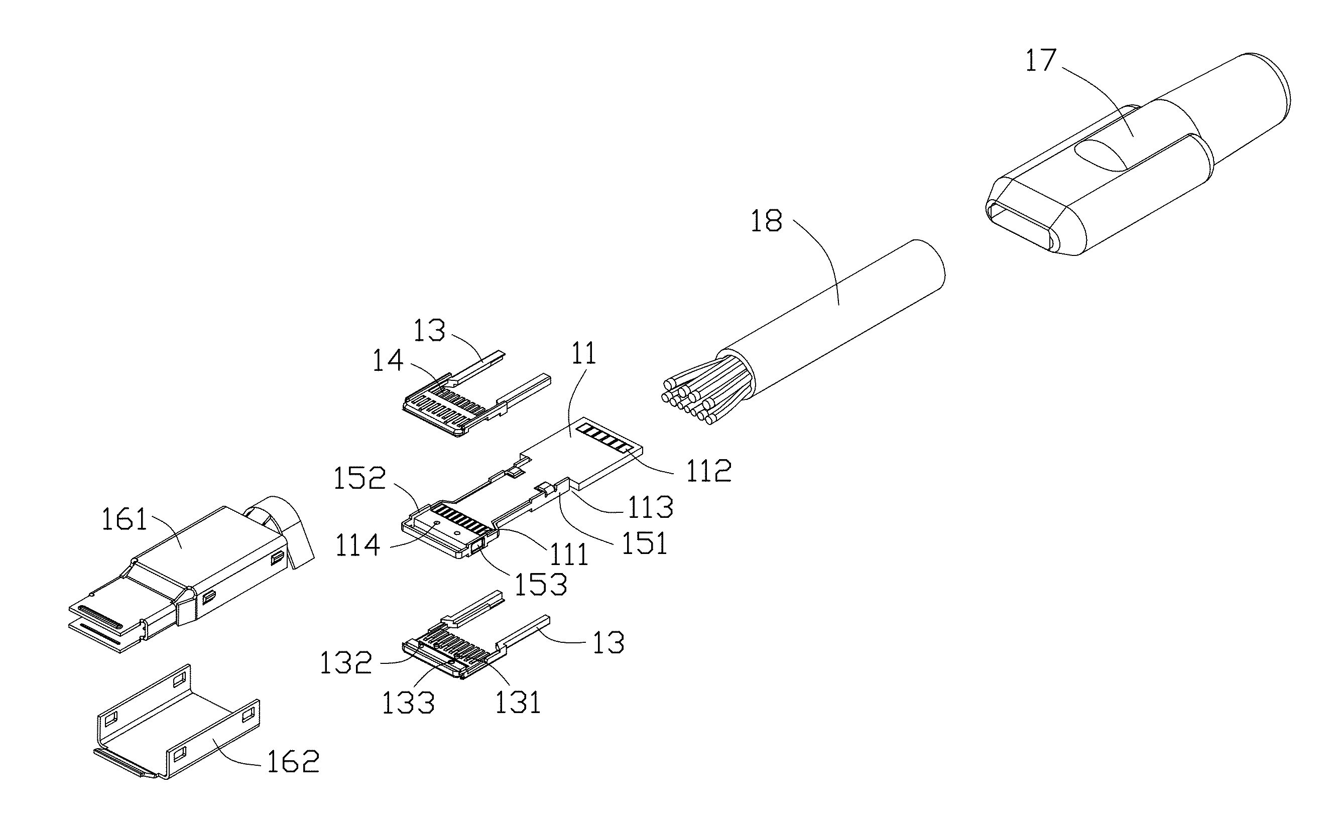
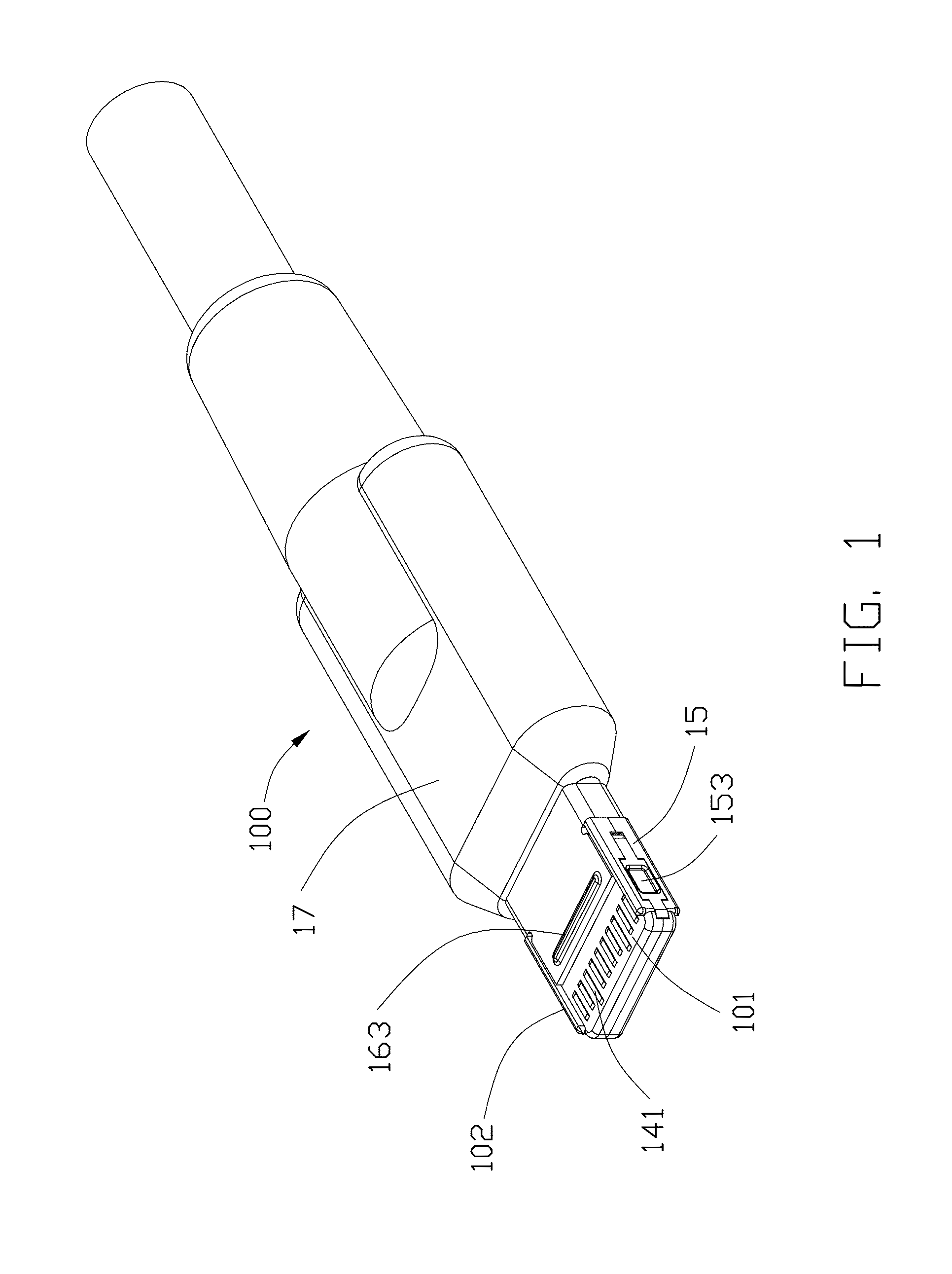
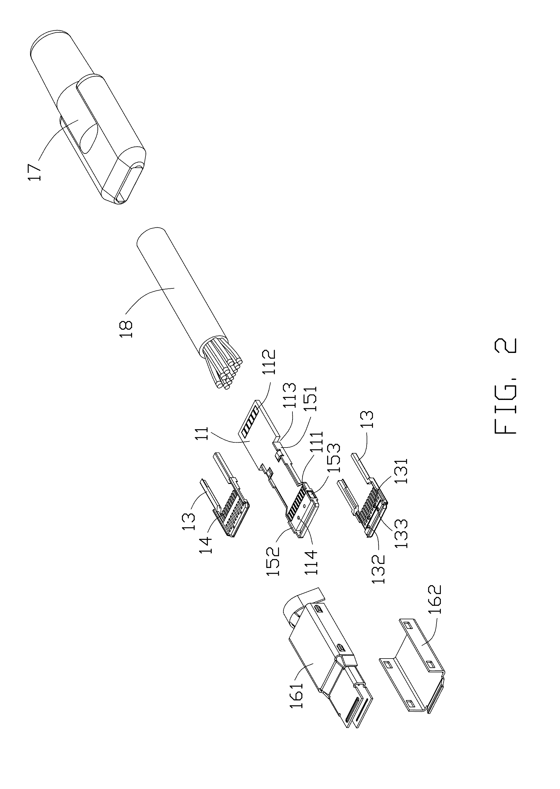
[0043]Referring to FIGS. 1-2, the instant invention discloses a plug connector 100 of a first embodiment, which is adapted for mating with a receptacle connector 200 as show in FIG. 3. The plug connector 100 includes a paddle card 11 with front circuit pads 111 and rear circuit pads 112 on two opposite surfaces, and a housing unit including a pair of identical housings 13 commonly sandwiching the paddle card 11 therebetween. Each of the housings 13 is equipped with a plurality of contacts 14 therein via an insert molding process wherein the contacts are mechanically and electrically connected to the corresponding front circuit pads 111, respectively. A metallic U-shaped V-Bus clip or power / grounding contact 15 surrounds the paddle card 11 except a rear end region of the paddle card 11. The rear end 151 of the clip 15 is mechanically received in and electrically terminated at a corresponding slot 113 of the paddle card 11, and a front portion 152 of the clip 15 defines a pair of rete...

third embodiment

[0048]FIGS. 11-12 show a third embodiment on the V-Bus / power contacts still with the latching function. The power contacts 65 of the receptacle connector 600 are of a blade type without deflection but with a retention recess 651 therein. In opposite, the plug connector 500 is equipped with the spring loaded power contacts 55 with outward arc portions 551 on two lateral sides for engagement within the corresponding retention recesses 651, respectively.

fourth embodiment

[0049]Referring to FIGS. 13-25 showing the instant invention, which discloses a plug connector 700 and a receptacle connector 800 mounted upon the printed circuit board.

[0050]Referring to FIG. 16, the plug connector 700 includes a paddle card 71 with circuit pads 711, 712 on two opposite surfaces. An insulative housing 72 located in front of the paddle card 71, is enclosed in a metallic shell 73. A cable 75 extends rearwardly from the paddle card 71 and includes therein a plurality of wires (not shown) respectively connected to a rear region of the paddle card 71. A cover 76 is overmolded on the shell 73, the paddle card 71 and the cable 75 to finalize the whole plug connector 700.

[0051]Combination with FIGS. 17-21, the insulative housing 72 defines a center slot 701 between two walls 721 each equipped with a plurality of deflectable contacts 73 in the corresponding passageways 722, respectively, each having a front contacting section 731 extending into the center slot 701 and a rea...


PUM


Abstract

A flappable plug connector and a complementary receptacle connector are provided wherein the plug connector defining a mating tongue, is made with a pair of insert molding housings which are associated with the contacts thereof, commonly sandwiching a paddle card therebetween with a pair of power contacts exposed on two opposite lateral sides to form a sub-assembly. The corresponding receptacle connector defines a receiving cavity to receive the mating tongue of the plug connector. The plug connector defines a V-Bus clip surrounding the mating tongue for power transfer and the receptacle connector includes a pair of deflectable power contacts by two sides of the receiving cavity.

Description

CROSS REFERENCE TO RELATED APPLICATIONS[0001]This application is a continuation-in-part of Ser. No. 14 / 477,889 filed Sep. 5, 2014, a continuation-in-part of Ser. No. 14 / 454,737 filed Aug. 8, 2014, a continuation-in-part of Ser. No. 14 / 337,180 filed Jul. 21, 2014, and claims the benefit of, and priority to, U.S. Provisional Patent Application No. 61 / 899,276, filed Nov. 3, 2013, No. 61 / 917,363, filed Dec. 18, 2013, the contents of which are incorporated entirely herein by reference. This application relates to another copending application under the attorney docket number US55260.BACKGROUND OF THE INVENTION[0002]1. Field of the Invention[0003]The present invention relates to an electrical connector, and more particularly to a flappable plug connector used with a receptacle connector.[0004]2. Description of Related Art[0005]US Patent Publication No. 20130095702A1 discloses a dual orientation plug connector, which has a connector tab with first and second major opposing sides and a plur...

Claims


Application Information

Patent Timeline
Patent Type & Authority Applications(United States)
IPC IPC(8): H01R24/60H01R13/6581
CPCH01R24/60H01R2107/00H01R13/6581H01R12/724H01R13/642H05K1/117H05K1/184H05K2201/10189
Inventor LITTLE, TERRANCE F.ZHAO, JIMCHENG, CHIH-PICHANG, CHUN-YISEDIO, STEPHEN
Owner FOXCONN INTERCONNECT TECH LTD
Why Eureka
Try Eureka