Coaxial dual function probe and method of use

a dual-functional, probe technology, applied in the field of tissue treatment devices and methods, can solve the problems of increasing the time of surgery and disassembly of the patient, and achieve the effect of improving the patient's condition

Active Publication Date: 2015-05-07
ANGIODYNAMICS INC
View PDF9 Cites 48 Cited by
  • Summary
  • Abstract
  • Description
  • Claims
  • Application Information

AI Technical Summary

Problems solved by technology

A limitation of such commercially available IRE probes is that such devices function primarily as either a bipolar probe device or a monopolar probe device, and there is typically very little, if any, cross-functionality between such devices, such that if a practitioner desires to use one device as a bipolar device and another device as a monopolar device, one electrosurgical device may have to be removed and replaced with a different device in order to switch between a bipolar and a monopolar treatment, thereby causing disruption to the patient and increased procedure time.
Another problem associated with current IRE devices is that during a single IRE ablation, a practitioner may desire to adjust the ablation volume of a target tissue while minimizing the potential disruption to a patient from the removal and reinsertion of all of the electrodes into the patient's tissue.

Method used


Image

  • Coaxial dual function probe and method of use
  • Coaxial dual function probe and method of use
  • Coaxial dual function probe and method of use

Examples


Embodiment Construction

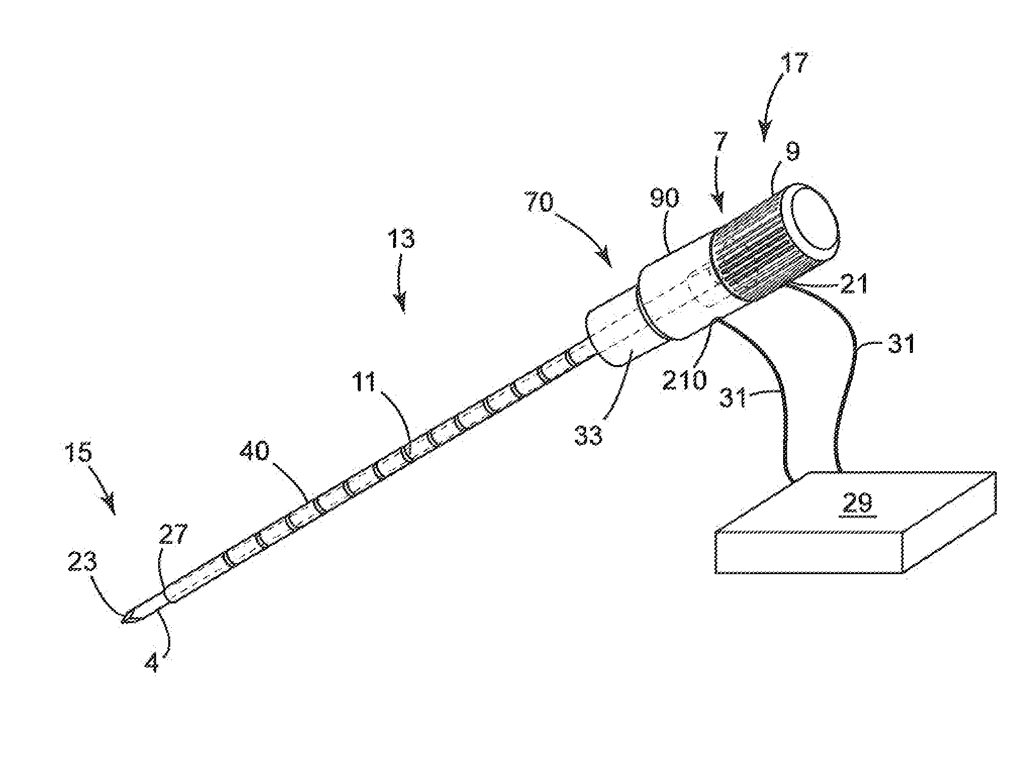
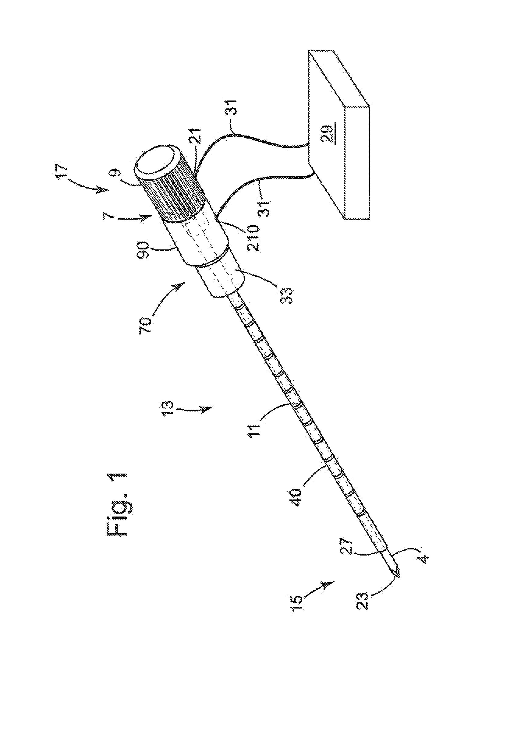
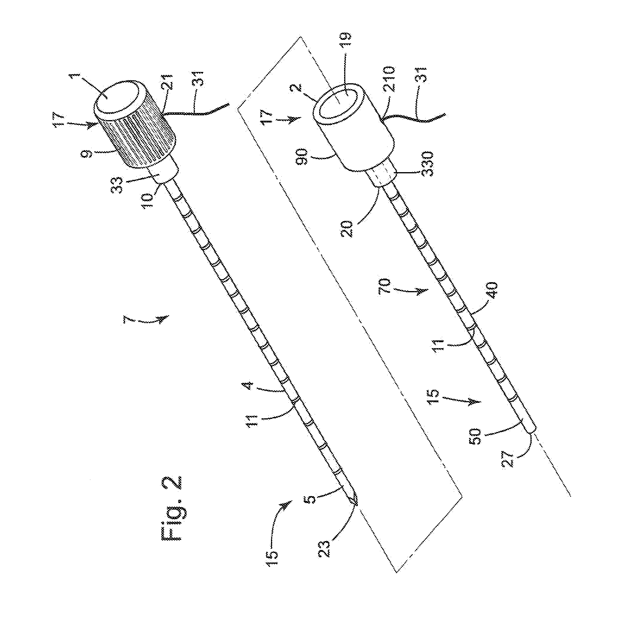
[0051]The present invention can be understood more readily by reference to the following detailed description and the examples included therein and to the Figures and their previous and following description. The drawings, which are not necessarily to scale, depict selected preferred embodiments and are not intended to limit the scope of the invention. The detailed description illustrates by way of example, not by way of limitation, the principles of the invention.

[0052]The skilled artisan will readily appreciate that the devices and methods described herein are merely exemplary and that variations can be made without departing from the spirit and scope of the invention. It is also to be understood that the terminology used herein is for the purpose of describing particular embodiments only and is not intended to be limiting.

[0053]Ranges can be expressed herein as from “about” to one particular value, and / or to “about” another particular value. When such a range is expressed, anothe...


PUM


Abstract

An energy delivery probe for use in tissue ablation and method of use is presented. The energy delivery device has at least a first energy delivery member and a second energy delivery member that have handle members positioned along a longitudinal axis, each handle member having a proximal and distal end. The distal end of the first handle member is releasably coupled to the proximal end of the second handle member and a portion of each member is defined in a coaxially surrounding relationship to each other along the longitudinal axis. The method of using the probe involves identifying a tissue to be ablated, providing the energy delivery probe, inserting at least a portion of the energy delivery probe into the identified tissue, delivering electrical energy through the energy delivery probe to the identified tissue, and ablating the identified tissue such that at least a first ablation zone is formed.

Description

CROSS REFERENCE TO RELATED APPLICATIONS[0001]This application claims priority under 35 U.S.C. 119(e) to U.S. application Ser. No. 13 / 150,586, filed on Jun. 1, 2011.BACKGROUND OF THE INVENTION[0002]The present application relates generally to devices and methods for tissue treatment using Irreversible Electroporation (IRE). More specifically, the application relates to devices and methods for treatment of tissue through the application of pulsed electric fields that create nonthermal cellular effects and that can be applied at a level of sufficient strength so as to result in ablation of tissue.[0003]The application of an electric field to transiently permeabilize cells is a method known as reversible electroporation. In reversible electroporation, membrane defects are created and later reseal, allowing a time when macromolecules can be introduced across the cell membrane. This has been used, for example, to insert genes into cells (electrogenetherapy), and to insert anti-cancer drug...

Claims


Application Information

Patent Timeline
Patent Type & Authority Applications(United States)
IPC IPC(8): A61B18/14
CPCA61B18/1487A61B2018/00916A61B2018/00613A61B2018/00577A61B2018/00982A61B17/3417A61B17/3421A61N1/327A61B18/1477A61B18/1815A61B2018/00434A61B2018/00517A61B2018/00583A61B2018/00791A61B90/36A61B2090/0807A61B2090/3966
Inventor WILLIS, JEFFREY R.
Owner ANGIODYNAMICS INC
Why Eureka
Try Eureka