Method and system for monitoring ablation of tissues

a tissue ablation and monitoring system technology, applied in the field of tissue ablation monitoring, can solve the problems of tissue thermal injury, radiofrequency ablation, overheating of the tissue,

Active Publication Date: 2008-05-06
TEL HASHOMER MEDICAL RES INFRASTRUCTURE & SERVICES
View PDF12 Cites 32 Cited by
  • Summary
  • Abstract
  • Description
  • Claims
  • Application Information

AI Technical Summary

Problems solved by technology

Cancer is a major cause of death in the modern world.
This ionic agitation creates friction and induces thermal injury to the tissue.
Radiofrequency ablation, however, is mainly applied to hepatic tumors, or tumors that are not close to a major blood vessel, due to its insufficient accuracy.
By special control of the time the focused ultrasound waves act on the tumor, resulting in an overheating of the tissue hence leading to its destruction.
Several characteristics of the above prior art thermal therapy devices, however, limit their ability to treat large volumes or regions close to important anatomical structures.
High temperatures close to the device surface often leads to undesirable physical effects of charring or vaporization in tissue.
Inadequate heating can occur at the target boundary due to rapid decreases in deposited power with increasing distance from the device.
Thus, the use of minimal invasive thermal therapy is limited by the ability to monitor, hence control the destruction process precisely while it is being administered.
These techniques, however, only measure the temperature at isolated locations and cannot show the temperature distribution in the volume surrounding the destructing device.
However, this MRI is an expensive procedure which imposes serious constraints to the surgical scenario.
A major disadvantage of this method is that it is limited to surfaces and it is difficult to apply this technique in minimal invasive procedure without significantly modifying the procedure's scenario.
These approaches, however, have failed to provide the information required for minimizing injury to normal tissue while ablating the tumor.

Method used


Image

  • Method and system for monitoring ablation of tissues
  • Method and system for monitoring ablation of tissues
  • Method and system for monitoring ablation of tissues

Examples


example 1

Blood Perfusion

[0109]In an experiment performed by the Inventors of the present invention, a 2 cm diameter tumor in a mouse was ablated for 15 minutes using a 10 watt laser operating in a pulsed mode of 1 second “on,” 1 second “off.” During the ablation, the emitted energy was 4500 joules. For a fifty percent transmission efficiency of the optical fiber, this amounts to 2250 joules, delivered to the tissue. A large portion of the incident energy is dispersed by blood perfusion. There is a considerable level of uncertainty of the exact amount of energy which is dispersed by blood perfusion, due to several factors, such as the tumor stage, which can be in a varying degree of necrosis; and the level of blood vessel coagulation induced by the laser irradiation.

[0110]Relevant perfusion data range from 5 to 50 (measured in units of ml blood per 100 g tissue per minute), depending on tissue characteristics [Gunnar Brix et al., “Regional Blood Flow, Capillary Permeability, and Compartmental...

example 2

Analysis of Ultrasound Images

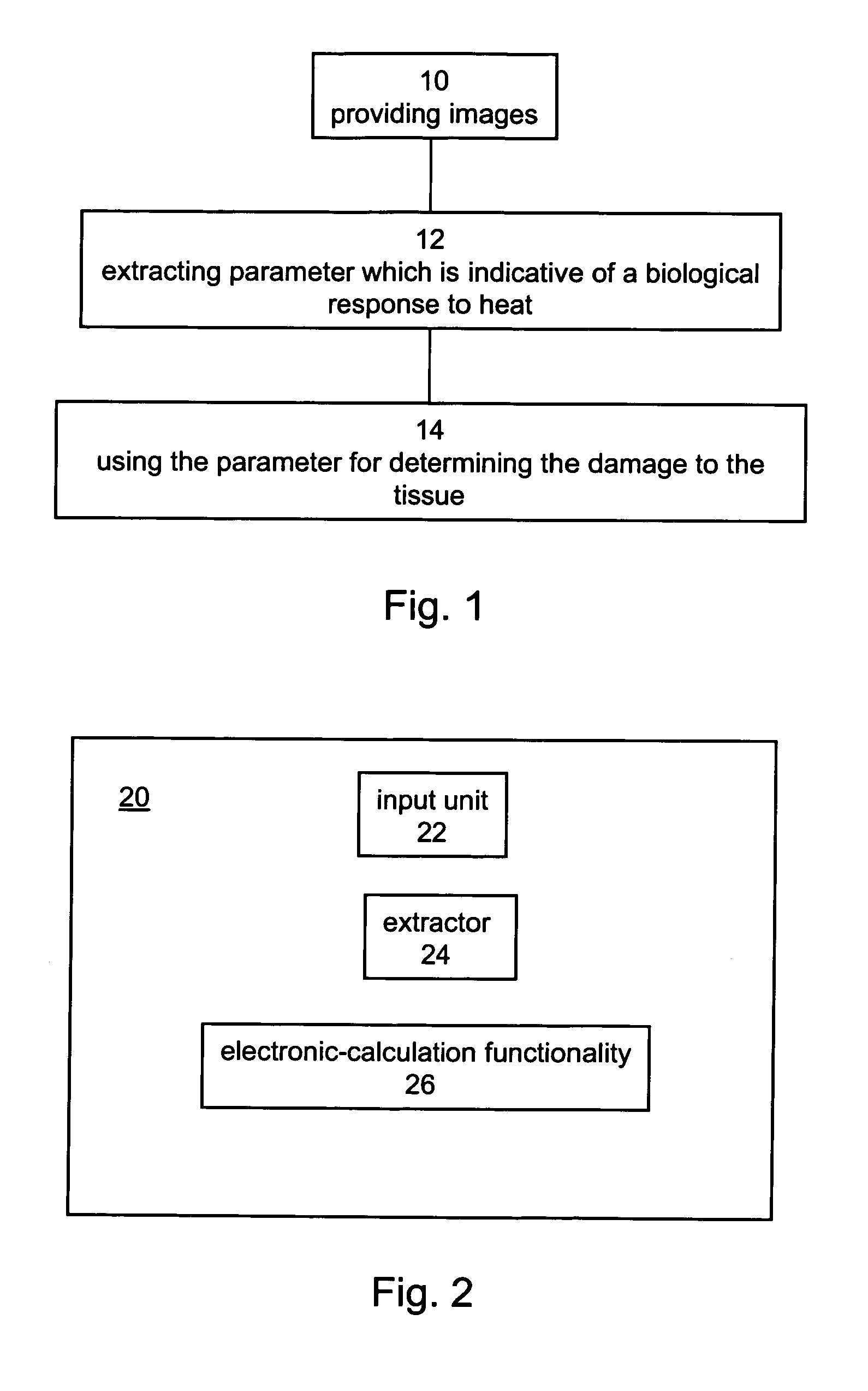
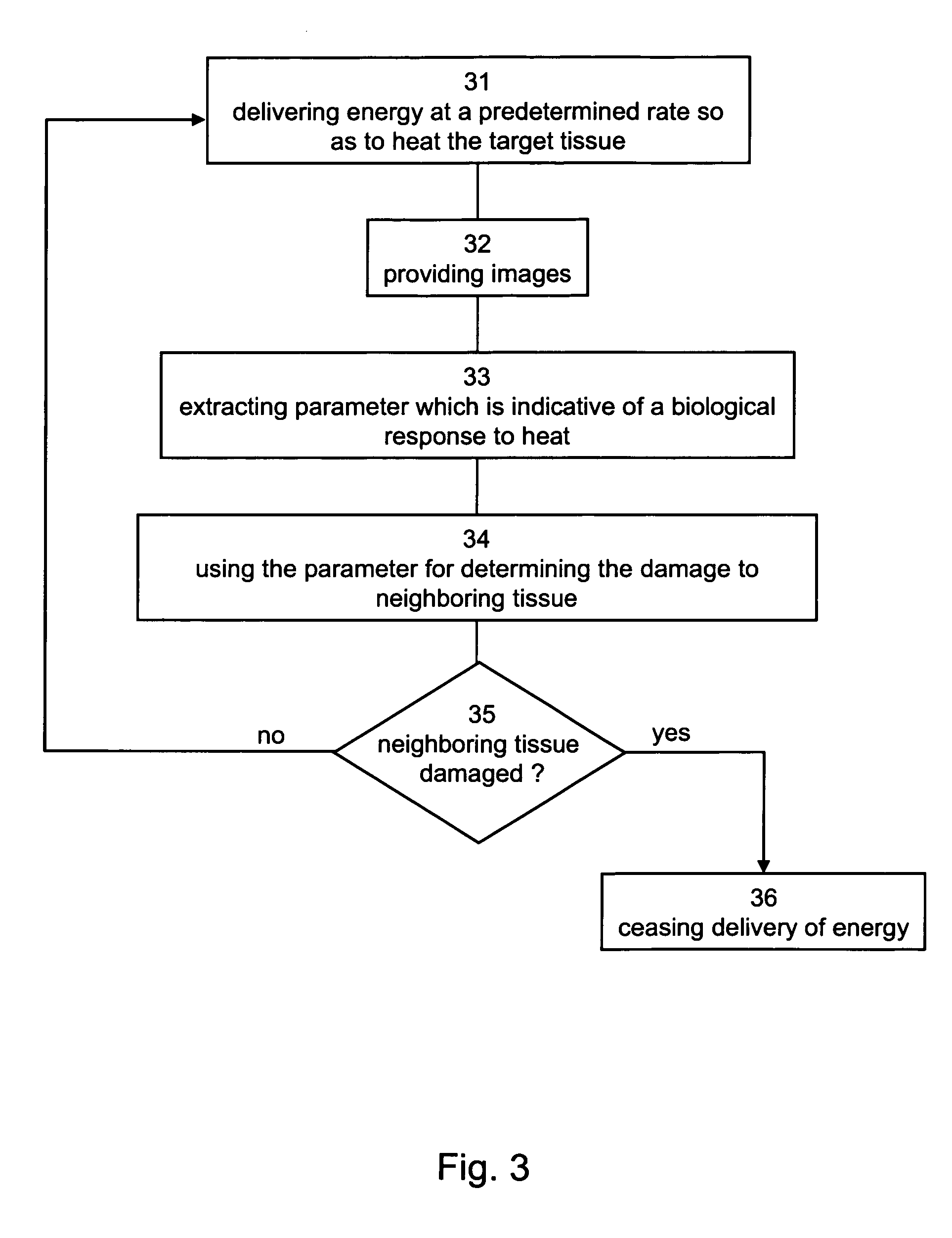
[0112]Following is a description of an algorithm, suitable for analyzing ultrasound images. The algorithm can be tangibly embodied by a machine-readable memory having a program of instructions executable by the machine for executing the algorithm.

[0113]It is to be understood that the algorithm presented in the present, example, including the number, order and nature of the assignments and criteria which are employed thereby, are not to be considered as limiting.

[0114]The algorithm is preferably executed by a data processor having an input unit for receiving image information. The image information is preferably a plurality of digital signals, representing gray levels or colors of picture elements (e.g., pixels) of the ultrasound image. In principle, the steps of the algorithm are preferably applied on several picture elements, more preferable on all picture elements of the neighboring tissue, most preferably on all the picture elements of the ultrasound ...

example 3

Ablating a Colon Cell Carcinoma by Laser

[0119]Materials and Methods

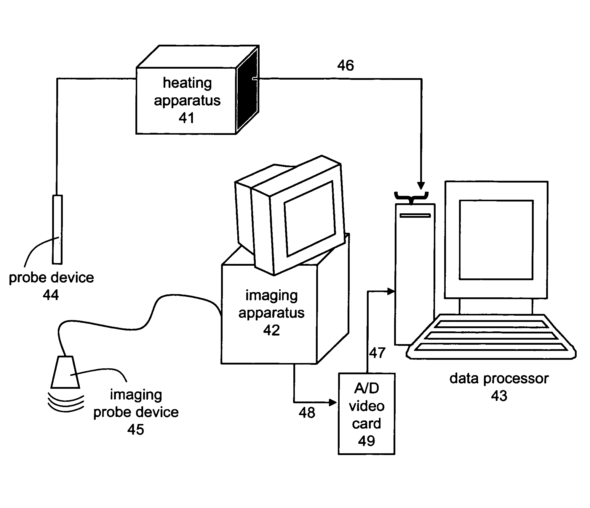
[0120]BALB / c mice were implanted subcutaneously with C26 colon cell carcinoma. Tumors were treated by a SHARPLAN 6020-diode laser system, emitting at 825 nm, using an interstitial fiber optic probe. During treatment, tissue effects were monitored and recorded by an ultrasound apparatus (Vivid3, General Electric) and the temperature was measured with thermocouples inserted in the tumor at different distances from the fiber optic probe end.

[0121]Twenty-four hours after treatment the mice were injected intraperitoneally with 1% Evans blue dye, and 24 hours later the mice were sacrificed, tumors were excised and 2-3 mm thick cross-section slices were cut. A section from the central area of each tumor was photographed with a color digital camera (model Camedia C-2000Z, Olympus) and compared with the ultrasound images obtained during monitoring. The injection of the dye into the blood system selectively stained viable tiss...


PUM


Abstract

A method of monitoring heat damage to a tissue during a heat ablation procedure is disclosed. The method comprising: providing images of the tissue, extracting at least one parameter being indicative of a biological response to heat, and using the parameter(s) for determining the heat damage to the tissue.

Description

FIELD AND BACKGROUND OF THE INVENTION[0001]The present invention relates to the monitoring of tissue ablation, and more particularly, to a method and system for monitoring ablation of tissue by determining a biological response of the tissue to heat.[0002]Cancer is a major cause of death in the modern world. Effective treatment of cancer is most readily accomplished following early detection of malignant tumors. Most techniques used to treat cancer (other than chemotherapy) are directed against a defined tumor site in an organ, such as brain, breast, ovary and colon, etc. Removal of a consolidated mass of abnormal cells is possible by surgical excision, heating, cooling, irradiative or chemical ablation.[0003]Minimal invasive thermal therapy is a potential treatment for solid internal malignancies. This type of therapy provides for shorter hospital stays, faster recovery and better cosmetic results. In thermal therapy, heat is produced by devices inserted directly into a target site...

Claims


Application Information

Patent Timeline
Patent Type & Authority Patents(United States)
IPC IPC(8): A61B8/00A61H1/00
CPCA61B8/0833A61B18/20A61B18/18A61B2019/5276A61N7/02A61B2090/378
Inventor ROSEMBERG, YOSSEFORENSTEIN, ARIE
Owner TEL HASHOMER MEDICAL RES INFRASTRUCTURE & SERVICES
Why Eureka
Try Eureka