Orbital welding torch systems and methods with lead/lag angle stop

a technology of orbital welding torch and angle stop, which is applied in the direction of manufacturing tools, soldering devices, auxilary welding devices, etc., can solve the problems of inability to simply and quickly readjust to a specific angle, inability to accurately measure lead or lag angle or establish repeatable reference points,

a technology of orbital welding torch and angle stop, which is applied in the direction of manufacturing tools, soldering devices, auxilary welding devices, etc., can solve the problems of inability to simply and quickly readjust to a specific angle, inability to accurately measure lead or lag angle or establish repeatable reference points,

US20150129579A1Active Publication Date: 2015-05-14LINCOLN GLOBAL INC

Image

  • Orbital welding torch systems and methods with lead/lag angle stop
  • Orbital welding torch systems and methods with lead/lag angle stop
  • Orbital welding torch systems and methods with lead/lag angle stop

Examples


Embodiment Construction

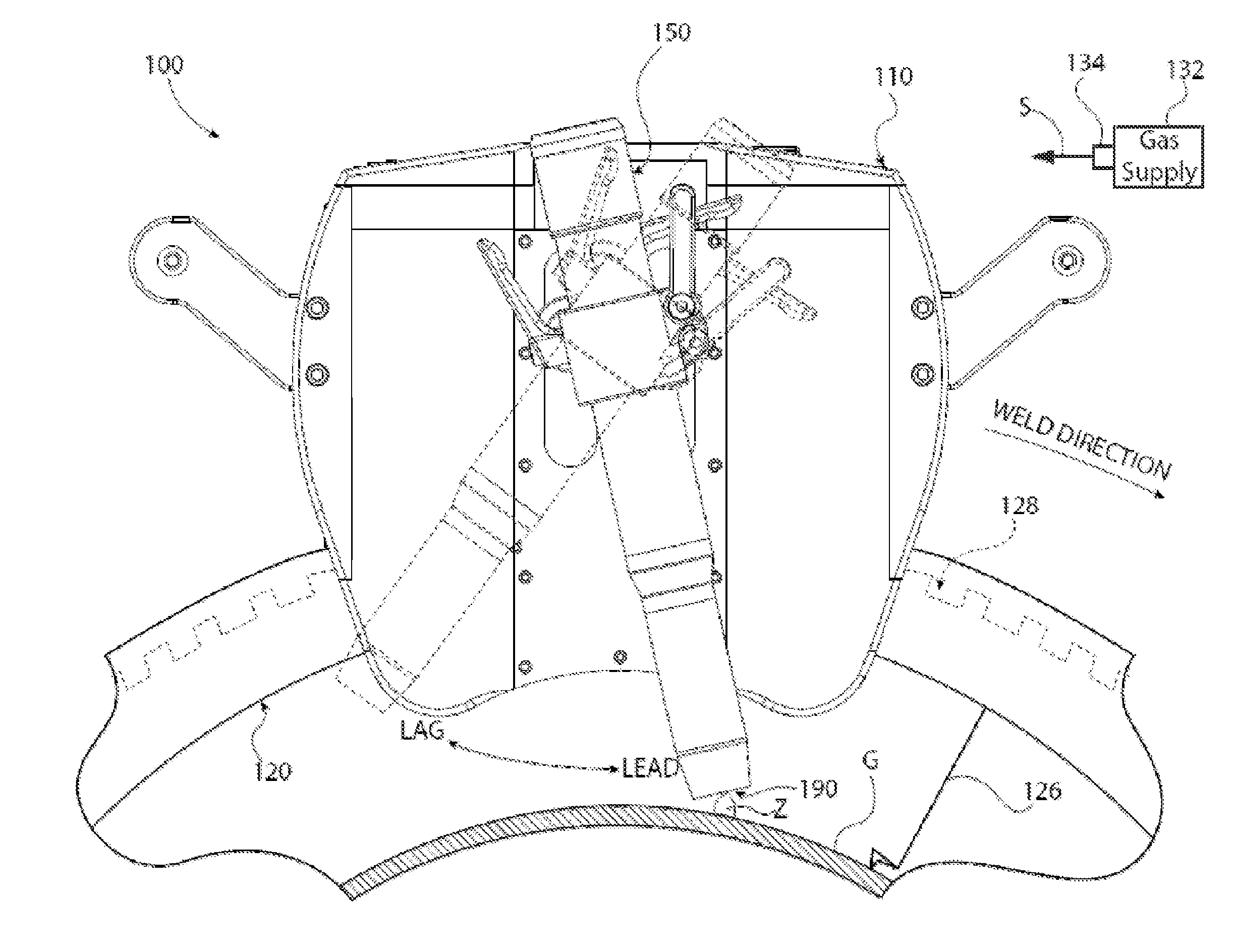
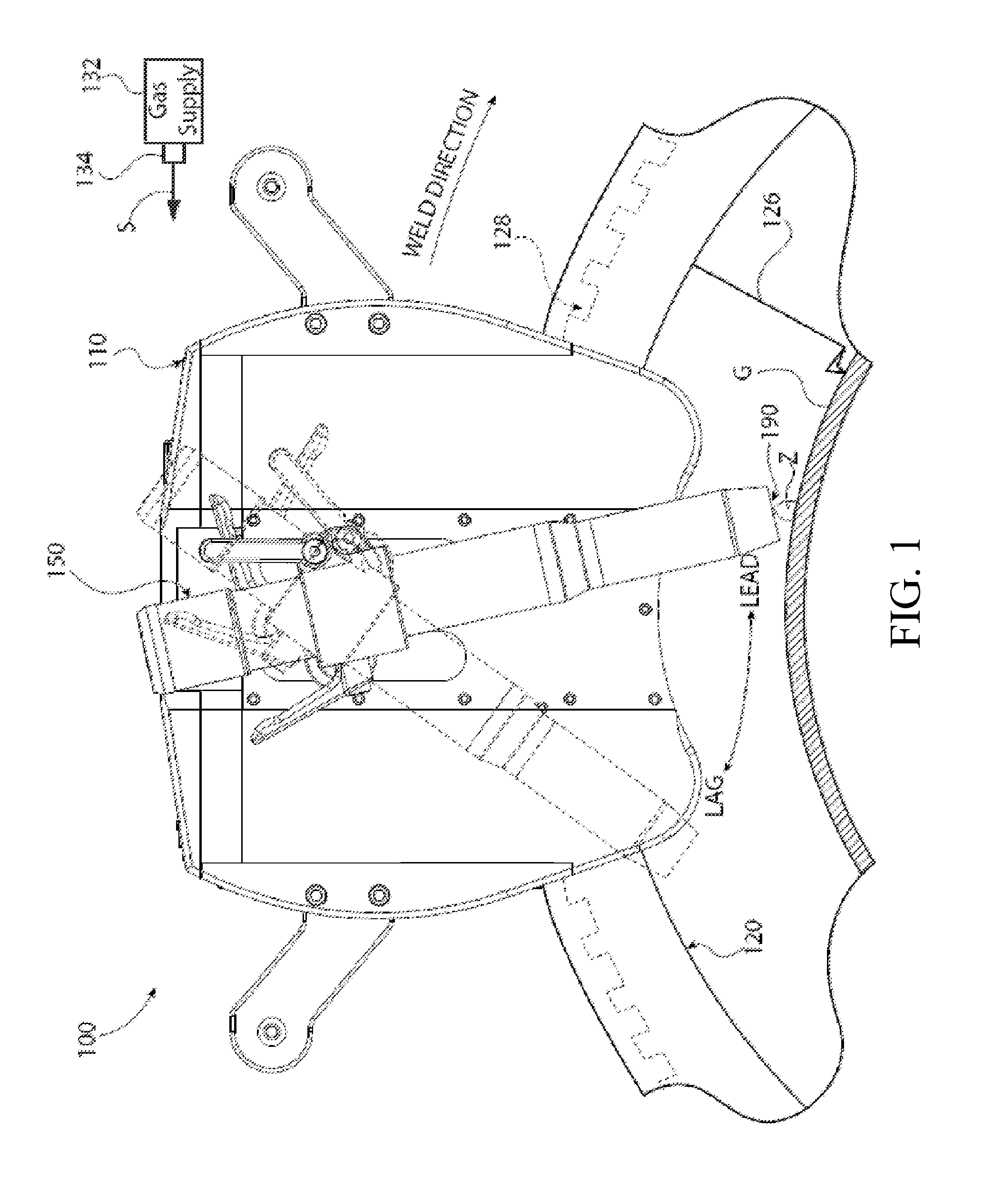
[0018]The disclosure herein generally pertains to systems and methods related to accurate, repeatable setting of welding torch lead and lag angles in orbital welding systems. Such systems and methods allow one or more torch head positions, including lead or lag angle, to be set to a set torch position using movable stops, known-position detents, and others. This enables an operator to quickly move the torch to or from multiple known positions, ensuring the torch angle will return to the same set torch position(s) each time. In some embodiments, an operator may accurately set the torch angle by viewing a measurable angle on a scale. Further, the components of the invention permit other adjustments, such as the torch offset in reference to a work piece, a torch height in relation to the work piece, and angles other than lead or lag such as a work or bevel angle.

[0019]Specifically, in one embodiment, a torch is coupled with a lead-lag coupler having at least one stop lug. A stop set wi...


PUM

PropertyMeasurementUnit
anglesaaaaaaaaaa
anglesaaaaaaaaaa
perimeteraaaaaaaaaa

Abstract

The invention described herein generally pertains to systems and methods related to repeatable and accurate setting of welding torch lead and lag positions, particularly with orbital welding systems. Specifically, a torch is coupled with a lead-lag coupler having a stop lug. A stop set with a stop pin is rotated to a desired position of lead or lag and secured. The lead-lag coupler, and torch which rotates therewith, are then unsecured and rotated until the stop lug contacts the stop pin. In this position, the torch is maintained at the desired angle. The stop pin remains in place throughout operation(s) to permit quick, accurate return to the desired angle if the torch is temporarily moved out of position.

Description

CROSS-REFERENCE TO RELATED APPLICATIONS AND INCORPORATION BY REFERENCE[0001]This U.S. patent application is a continuation of and claims the benefit of U.S. provisional patent application 61 / 902,553 filed on Nov. 11, 2013, which is incorporated herein by reference in its entirety.TECHNICAL FIELD[0002]In general, the present invention relates to controlling the angle of an electrode in connection with an orbital welding system. More particularly, the present invention relates to accurately and repeatably angling a welding torch in an orbital welding system, and enabling quick return to one or more selected angles based when the torch is moved.BACKGROUND OF THE INVENTION[0003]In industrial production, welding may involve raising, cladding, building up, filling, hard facing, overlaying, joining, and other welding applications. When confronted with a work piece having a curved surface, an orbital welding process may be used to rotate the welding head to apply a weld to the curved surfac...

Claims


Application Information

Patent Timeline
14 May 2015
Publication
US20150129579A1
IPC
B23K9/028; B23K9/12; B23K9/32
CPC
B23K9/0286; B23K9/122; B23K9/328; B23K9/0282; B23K37/0217; B23K2101/10
Inventors
TRAVER, RICHARD DEAN