

Image forming apparatus
- Summary
- Abstract
- Description
- Claims
- Application Information
AI Technical Summary
Benefits of technology
Problems solved by technology
Method used
Image

Examples
embodiment 1
[0015]In the following, embodiments of the present invention will be described with reference to the drawings.
(1) Image Forming Portion
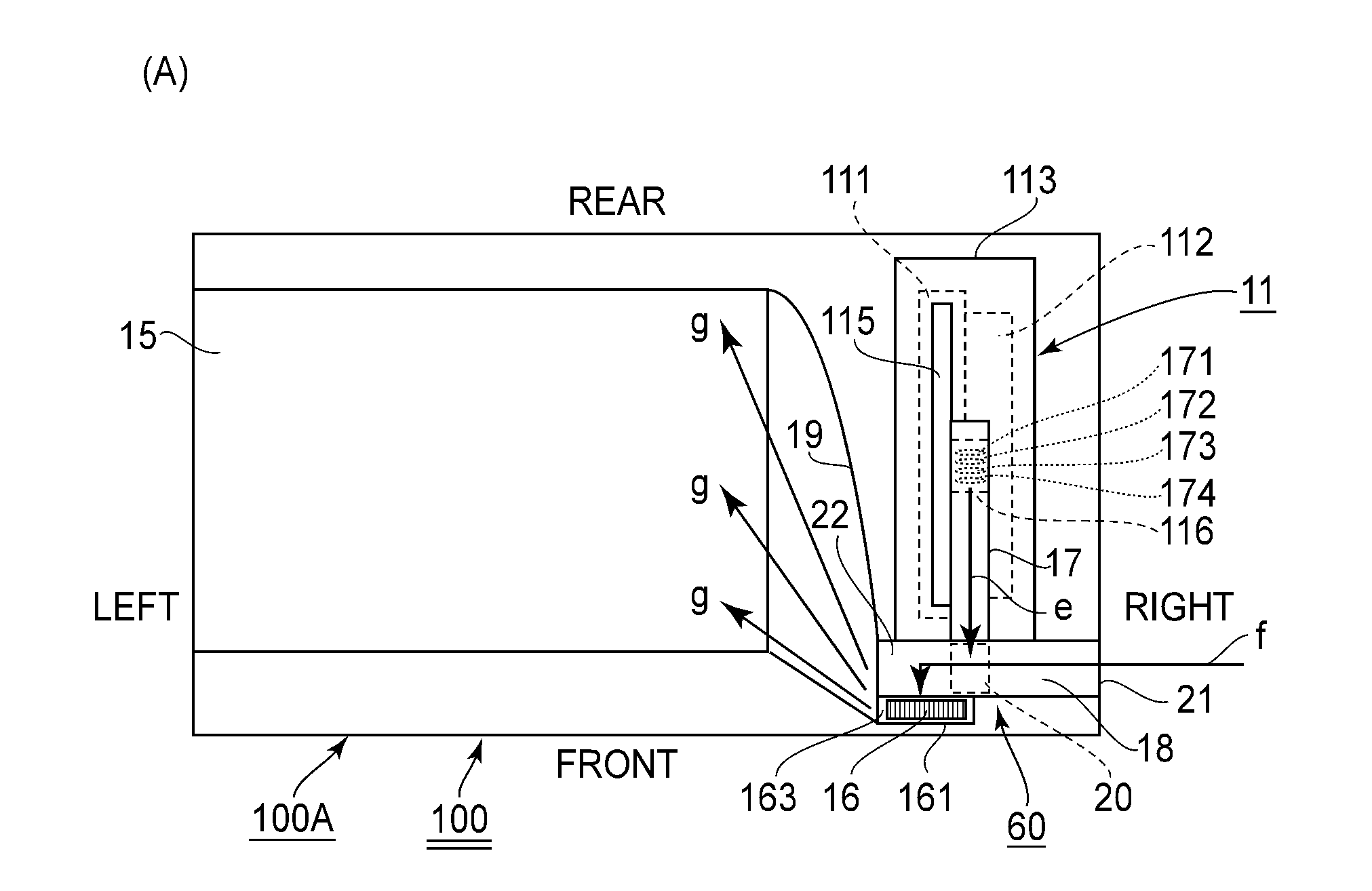
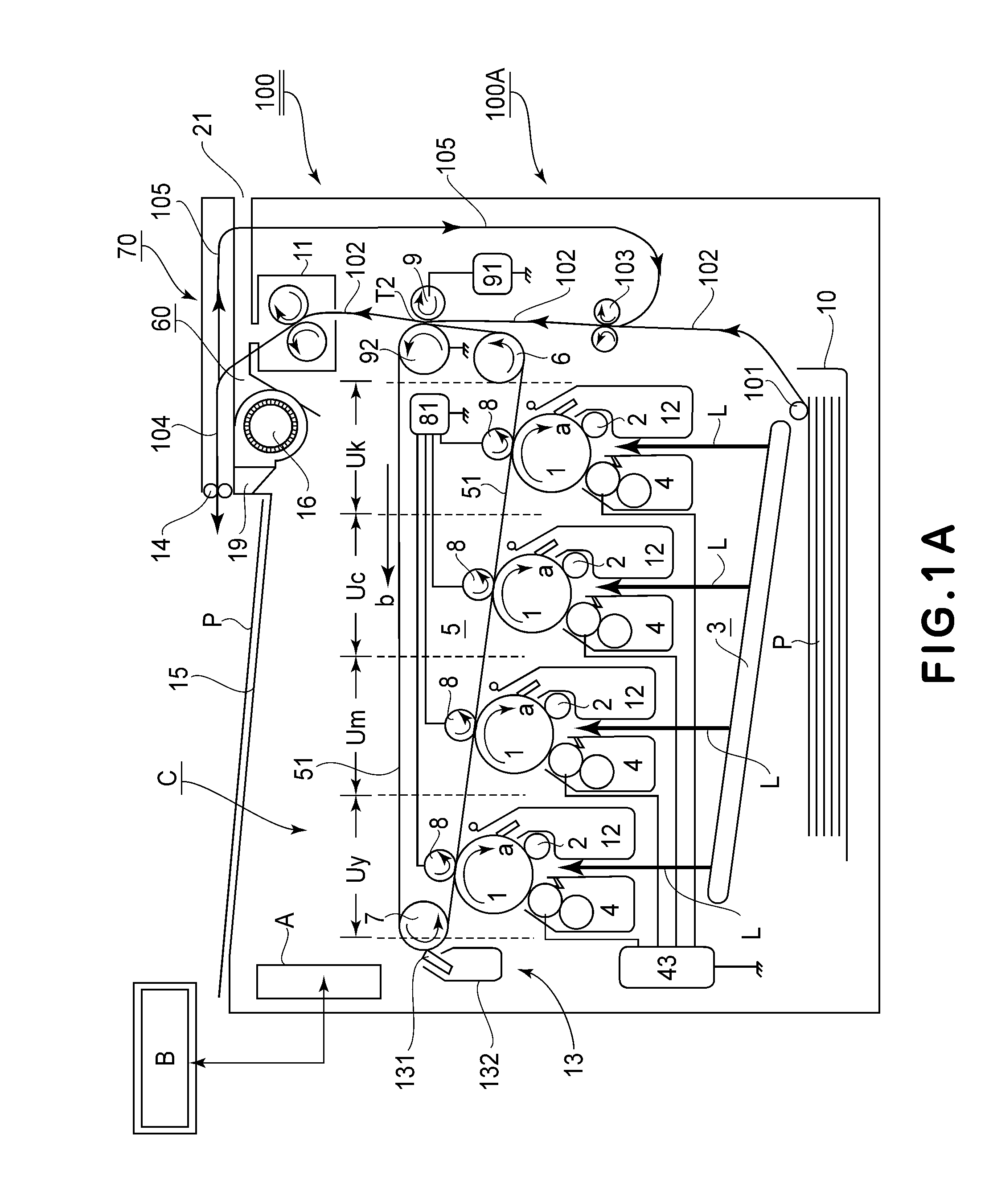
[0016]FIG. 1A is a schematic longitudinal front view showing a schematic structure of an image forming apparatus 100 in this embodiment. This image forming apparatus 100 is a color laser beam printer of an electrophotographic type in which a process speed is 200 mm / sec and 35 ppm. That is, an image forming operation is performed depending on electrical image information inputted from an external host device B such as a personal computer into a control circuit portion A to form a full-color toner image or a monochromatic toner image on a recording material P, and then the recording material P is outputted as an image-formed product (print).
[0017]With respect to the image forming apparatus 100 and constituent members thereof, a front (surface) side refers to a front side with respect to a direction perpendicular to the drawing sheet of FIG. 1. A rear (...
PUM
 Abstract
Description
Claims
Application Information