Insulating sealing element for head-of-wall joints

Inactive Publication Date: 2015-05-21
HILTI AG
View PDF20 Cites 19 Cited by
  • Summary
  • Abstract
  • Description
  • Claims
  • Application Information

AI Technical Summary

Benefits of technology

[0016]It is an object of the sealing element for insulating head-of-wall joints of the present invention to prevent the spread of sound, noise, fire, super-heated gases, flames and/or smoke in these areas.
[0017]It is an object of the sealing element for acoustical and/or thermal insulating head-of-wall joints of the present invention to provide more effective insulating by providing attachment of the insulating material to the metal track only in the central upper portion thereof or at the lowermost edges of the track side walls without any attachment whatsoever to th

Problems solved by technology

Head-of-wall joints often present a serious challenge in terms of reducing or preventing the spread of smoke and fire during a building fire.
So-called head-of-wall joints pose a number of challenges for the fireproofing industry.
Although the distance between the horizontally extending track at the top of the wall is often fixed in relationship to the ceiling, the gypsum wallboards are subject to expansion and contraction due to motion of other building components, ground settling, or other causes.
All of these approaches, however, are relatively labor intensive and thus expensive.
Thus, and although construction joints and gaps are generally sealed in some manner (e.g., mineral wool and/or elastomeric coatings; see also, U.S. Patent Application No. 2006/0137293 to Klein), there are relatively few products and methods available that effectively and efficiently seal head-of-wall construction joints and gaps to thereby significantly enhance the ability of such joints and gaps to withstand smoke and fire penetration.
In particular, there are very few products and metho

Method used


Image

  • Insulating sealing element for head-of-wall joints
  • Insulating sealing element for head-of-wall joints
  • Insulating sealing element for head-of-wall joints

Examples


Example

DETAILED DESCRIPTION OF THE DRAWINGS

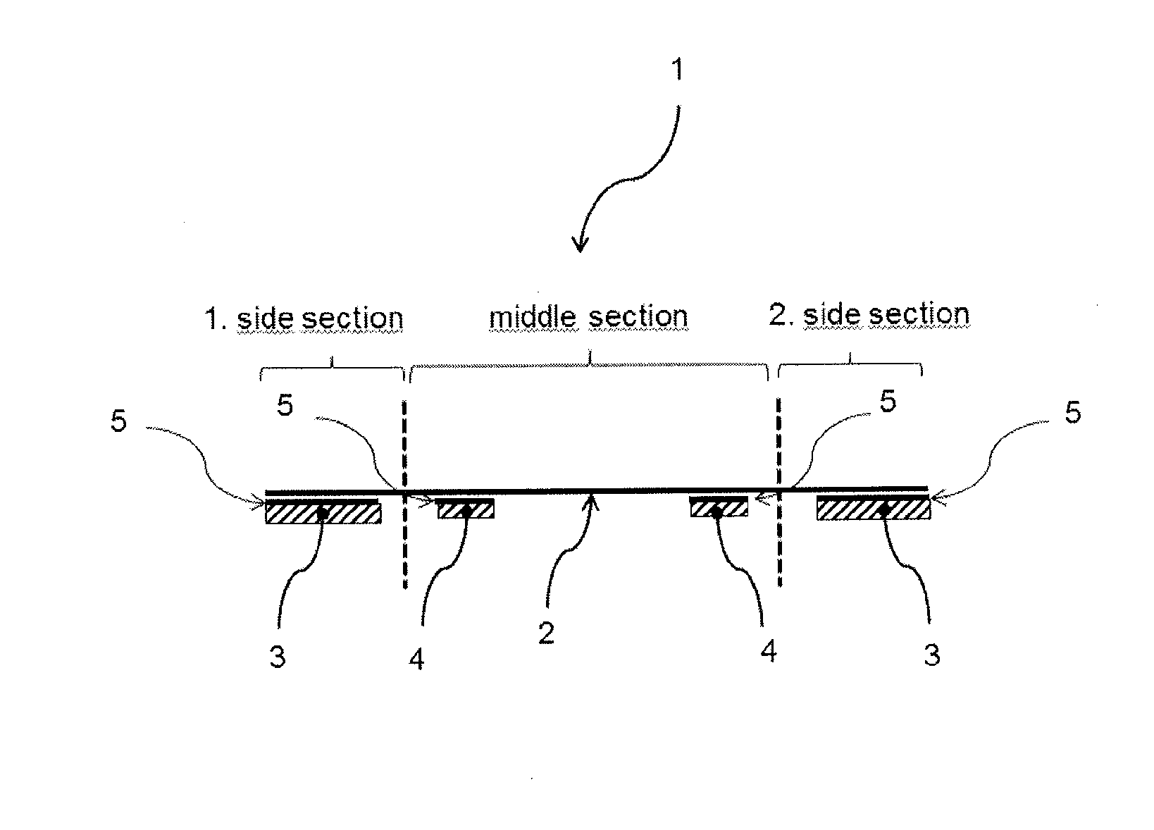
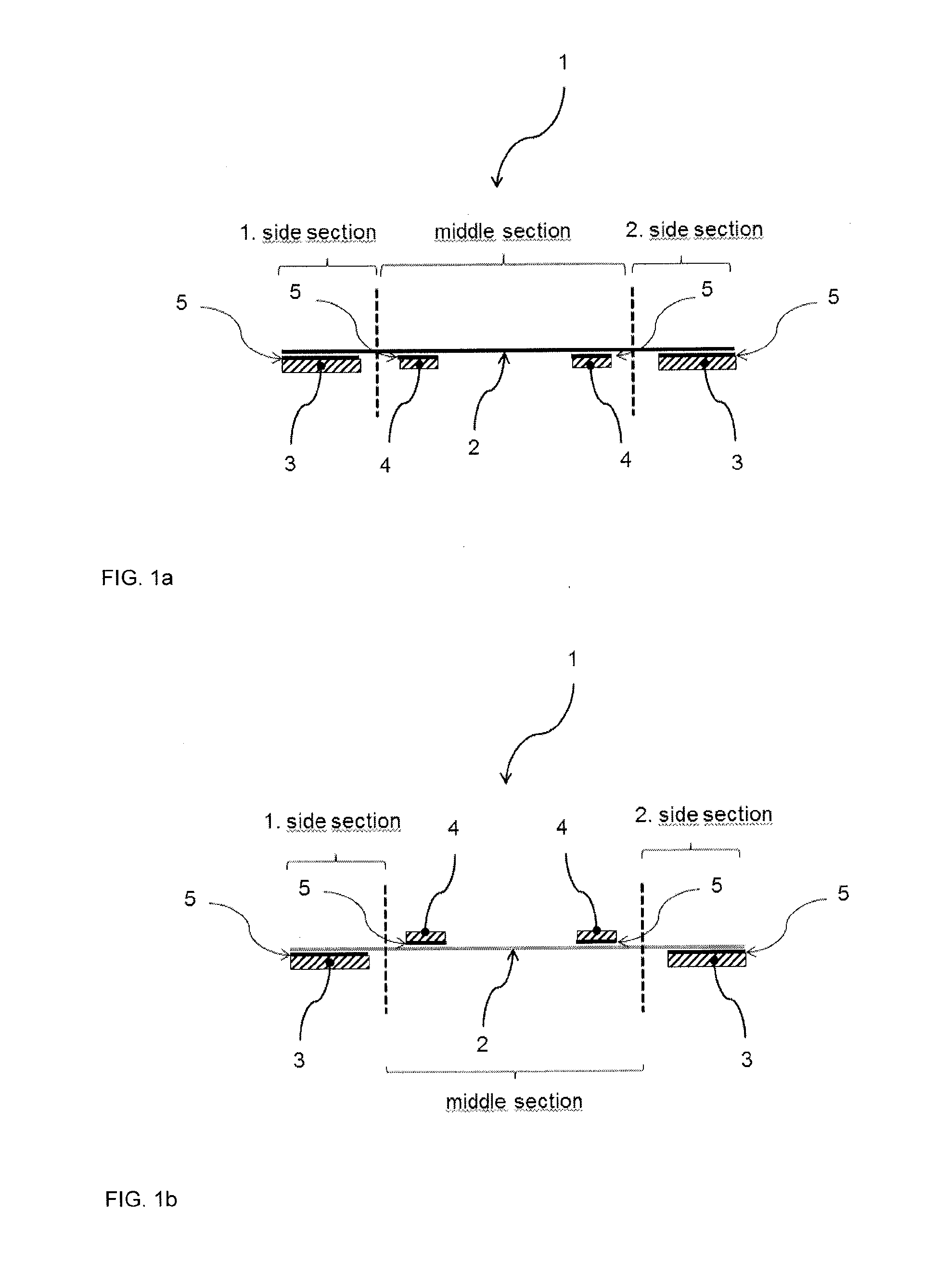
[0055]FIG. 1a illustrates an insulating strip assembly 1, which is also referred to herein as insulating strip. The insulating strip 1 is an elongated strip assembly that preferably is constructed as an integrated assembly of multiple components. The insulating strip 1 may be supplied on a roll, in a folded arrangement or any other suitable manner. Preferably, the insulating strip 1 is provided as a separate component that is applied to a head-of-wall on site, as is described in greater detail below.

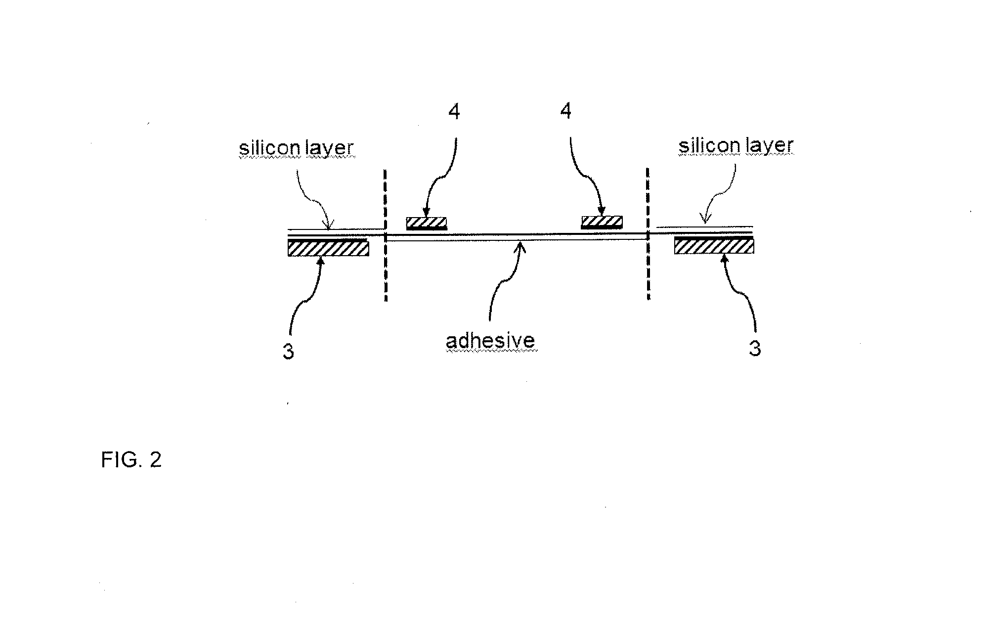
[0056]The illustrated insulating strip 1 includes fire-resistant material strips 3 and 4. All fire-resistant strips 3 and 4 are positioned on the same face of the support layer 2 spaced apart from each other. The fire-resistant strips 4 are arranged at a certain distance from each other to form a section inbetween where no insulating material is arranged. The insulating strips 3 and 4 may be secured to the support layer 2 by adhesives 5 applied to the ...


PUM

PropertyMeasurementUnit
Electrical resistanceaaaaaaaaaa
Widthaaaaaaaaaa
aaaaaaaaaa

Abstract

An insulating strip is disclosed. The insulating strip includes a support layer and a plurality of insulating material strips secured to the support layer where the plurality of insulating material strips are spaced apart from each other.

Description

[0001]This application claims the benefit of U.S. Provisional Application No. 61 / 905,711, filed Nov. 18, 2013, the disclosure of which is expressly incorporated by reference herein.BACKGROUND AND SUMMARY OF THE INVENTION[0002]The present invention deals generally with the field of acoustical or firestopping insulation for head-of-wall joints, including, possibly, intumescent components.[0003]In the building construction trade, a head-of-wall joint (also sometimes referred to as a top-of-wall joint) refers to the linear junction or interface existing between a top section of a framing or wallboard wall assembly and the ceiling, where the ceiling may be a next-level floor or corrugated pan roof deck, for example. Head-of-wall joints often present a serious challenge in terms of reducing or preventing the spread of smoke and fire during a building fire. In this regard and in common practice, a wall to ceiling connection of many newly constructed buildings consists essentially of metal ...

Claims


Application Information

Patent Timeline
IPC IPC(8): E04B1/94E04B1/68
CPCE04B1/6801E04B1/948E04B2/7411Y10T428/23Y10T428/24802
Inventor MUENZENBERGER, HERBERTSCHULZE, PETERSIMON, SEBASTIANPAETOW, MARIOKLEIN, MANFRED
Owner HILTI AG
Why Eureka
Try Eureka