Magnetron and method of manufacturing magnetron anode vane

Active Publication Date: 2009-06-18
PANASONIC CORP
View PDF11 Cites 0 Cited by
  • Summary
  • Abstract
  • Description
  • Claims
  • Application Information

AI Technical Summary

Benefits of technology

[0021]According to the configuration, the brazing material spreading prevention groove is formed on the anode vane, and thus it is possible to prevent the residual brazing material from spreading to the front end part of the anode vane when the anode vane is brazed on the inner peripheral surface of the anode cylinder. Thereby, non-uniformity in thickness of the anode vanes caused by the residual brazing material is suppressed, and electrostatic capacity between the anode vanes adjacent to each other becomes substantially constant. Thus, it is possible to obtain stable resonant frequency. In addition, it becomes easy to perform adjustment for obtaining the stable resonant frequency in that non-uniformity in initial frequency of the time when t

Problems solved by technology

In addition, it becomes easy to perform adjustment for obtaining the stable resonant frequency in that

Method used


Image

  • Magnetron and method of manufacturing magnetron anode vane
  • Magnetron and method of manufacturing magnetron anode vane
  • Magnetron and method of manufacturing magnetron anode vane

Examples


Example

Embodiment 1

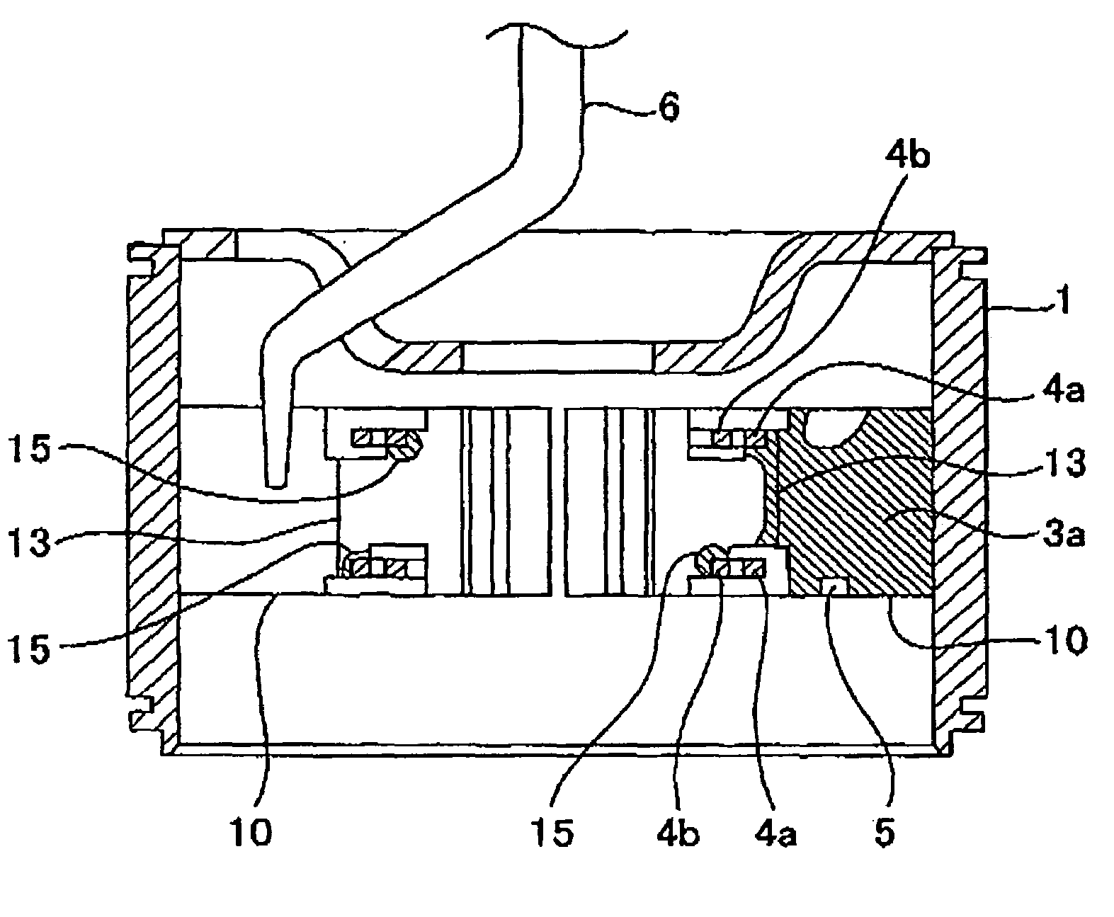
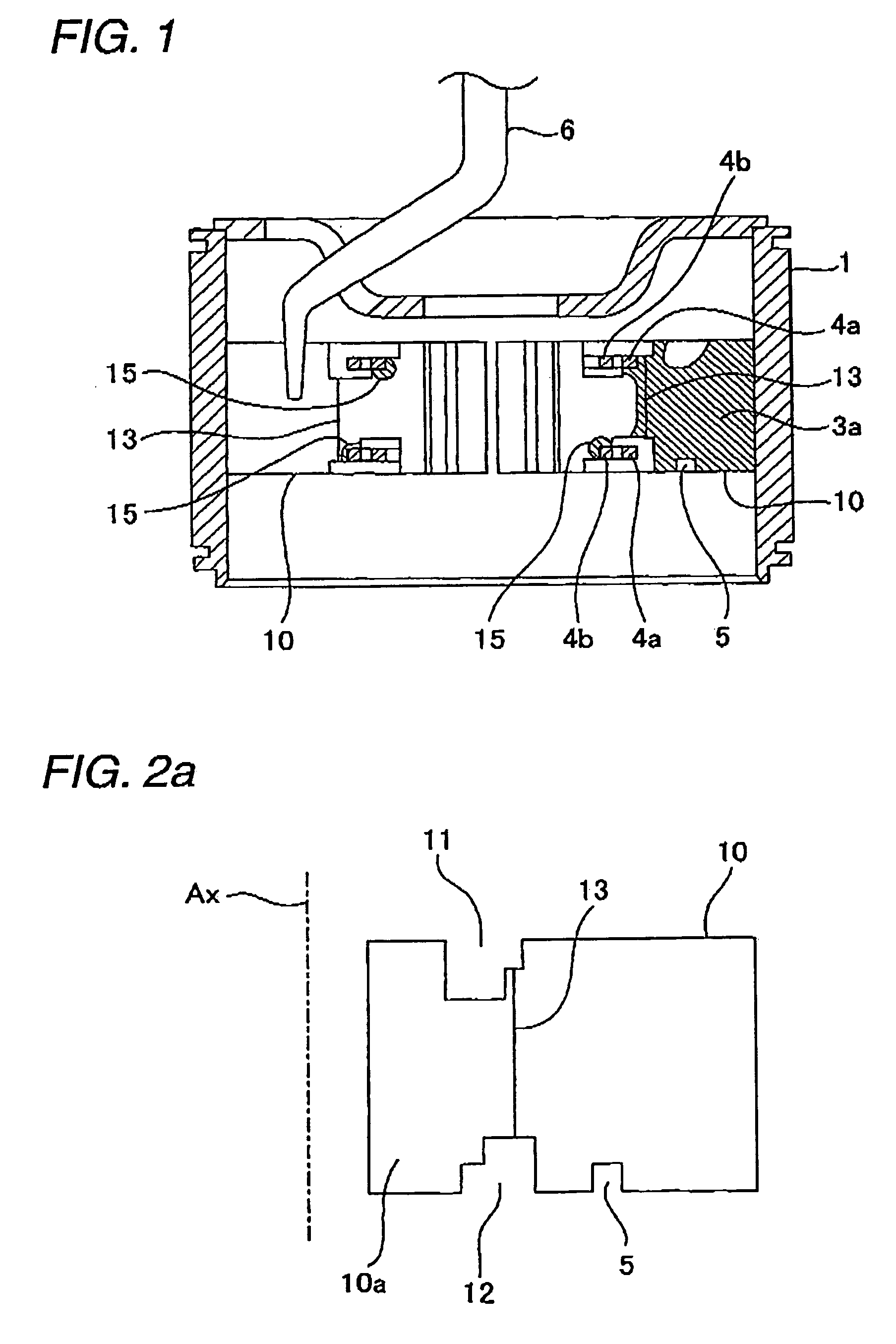
[0040]FIG. 1 is a cross-sectional view illustrating a schematic structure of the magnetron according to an embodiment 1 of the invention. In this drawing, common elements with FIG. 12 described above will be referenced by the same reference numerals and signs. The magnetron of the embodiment has an anode vane 10 configured so that a residual brazing material 3a does not spread to a front end part 10a. The anode vane 10 is shown in FIG. 2a. As shown in this drawing, the anode vane 10 includes a linear groove 13 (hereinafter, it is referred to as a ‘brazing material spreading prevention groove’) formed parallel to a direction of a central axis Ax between strap ring inserting portions 11 and 12. The strap ring inserting portions 11 and 12 are formed in a groove shape on an upper end and a lower end close to the central axis Ax in a lengthwise direction. The brazing material spreading prevention groove 13 is provided on one surface or both surfaces of the anode vane 10. In t...

Example

Embodiment 2

[0048]FIG. 4 is a view illustrating an anode vane of the magnetron according to an embodiment 2 of the invention. In this drawing, common elements with FIG. 2a described above will be referenced by the same reference numerals and signs. The magnetron of the embodiment, in the same manner as the magnetron of the embodiment 1, has an anode vane 16 configured so that a residual brazing material 3a does not spread to a front end part 16a.

[0049]In the anode vane 16, there is provided a linear groove 17 (hereinafter, it is referred to as a ‘brazing material spreading prevention groove’) that interconnects a part of a strap ring inserting portion 11 for brazing a strap ring 4a and a part of a strap ring inserting portion 12 for brazing a strap ring 4b. The strap ring inserting portion 11 is formed in a groove shape on an upper end close to the central axis Ax in a lengthwise direction, and the strap ring inserting portion 12 is formed in a groove shape on a lower end close to ...

Example

Embodiment 3

[0052]FIG. 5 is a view illustrating an anode vane of the magnetron according to an embodiment 3 of the invention. In this drawing, common elements with FIG. 4 described above will be referenced by the same reference numerals and signs. The magnetron of the embodiment, in the same manner as the magnetron of the embodiments 1 and 2, has an anode vane 18 configured so that a residual brazing material 3a does not spread to a front end part 18a.

[0053]The anode vane 18 includes not only the residual brazing material spreading prevention groove 17, which is the same as that of the anode vane 16 of the magnetron according to the embodiment 2, but also a residual brazing material guiding portion 19 which collects the residual brazing material 3a and guides the material to the residual brazing material spreading prevention groove 17. The residual brazing material guiding portion 19 is parallel to the lengthwise direction of the anode vane 18, and is formed in a linear shape that ...


PUM


Abstract

In each anode vane 10, there is provided the brazing material spreading prevention groove 13 that interconnects the strap ring inserting portions 11 and 12 in parallel to the direction of the central axis Ax. With such a configuration, it is possible to prevent the residual brazing material 3a from spreading to the front end part 10a of the anode vane 10 when each anode vane 10 is brazed on the inner peripheral surface of the anode cylinder 1. Therefore, non-uniformity in thickness of the anode vanes 10 caused by the residual brazing material 3a is suppressed, and electrostatic capacity between the anode vanes 10 adjacent to each other becomes substantially constant. Thus, it is possible to obtain stable resonant frequency. In addition, it becomes easy to perform adjustment for obtaining the stable resonant frequency in that non-uniformity in initial frequency of the time when the magnetron is completely assembled decreases.

Description

BACKGROUND OF THE INVENTION[0001]1. Field of the Invention The present invention relates to a magnetron used in microwave applications such as a microwave oven and a method of manufacturing an anode vane of the magnetron.[0002]2. Description of the Related Art[0003]FIG. 12 is a cross-sectional view illustrating a schematic structure of a known magnetron. In addition, FIG. 13 is a partial sectional perspective view illustrating an assembly state of the anode structure of the magnetron shown in FIG. 12. In FIGS. 12 and 13, a plurality of anode vanes 2 are brazed on an inner peripheral surface of an anode cylinder 1 by a high melting point brazing material 3 and are protruded toward a central axis of the anode cylinder 1. In the anode vanes 2, two large and small concentric strap rings 4a and 4b are alternately brazed on an upper end and a lower end thereof. In addition, in at least one of the anode vanes 2, a concave groove 5 is formed, and one end part of a microwave guide-out conduc...

Claims


Application Information

Patent Timeline
IPC IPC(8): H01J23/02H01J25/587H01J9/14
CPCH01J23/20H01J25/587H01J23/22
Inventor SAITOU, ETSUOKUWAHARA, NAGISAISHII, TAKESHI
Owner PANASONIC CORP
Why Eureka
Try Eureka