Vehicle body frame structure for all-terrain vehicle

Active Publication Date: 2005-08-18
HONDA MOTOR CO LTD
View PDF16 Cites 11 Cited by
  • Summary
  • Abstract
  • Description
  • Claims
  • Application Information

AI Technical Summary

Benefits of technology

[0036] According to this embodiment, the rigidity of the side cover comprising the body cover, the floor step, the front fender, the side cover, and the cover member is further enhanced, and resonance of the side cover can be prevented. Also, by removing only the cover member, it is possible to more easily expose a front portion of the engine to the exterior. For example, it is possible to easily perform an adjustment at an operating position adjusting portion of a clutch provided at a front portion of the engine, and the maintainability of the power unit can be further enhanced.
[0037] In another embodiment, the cover member is supported by only the body cover, the floor step, and the front fender. Conventionally, where the cover member is mounted to the vehicle body frame, mount portions such as stays for the cover member must be provided on the vehicle body fra

Problems solved by technology

For example, in the case where support portions for the steering shaft are provided respectively on the side of the upper vehicle body frame 202 and on the side of the lower vehicle body frame 203 in the figure, the arrangement in which the support portions are not present on the same frame side makes it difficult to enhance the mounting accuracy of the steering shaft.
One problem with this disclosure is that the upper arms are supported

Method used


Image

  • Vehicle body frame structure for all-terrain vehicle
  • Vehicle body frame structure for all-terrain vehicle
  • Vehicle body frame structure for all-terrain vehicle

Examples


Example

[0063] Embodiments of the present invention will be described hereinafter with reference to the accompanying drawings.

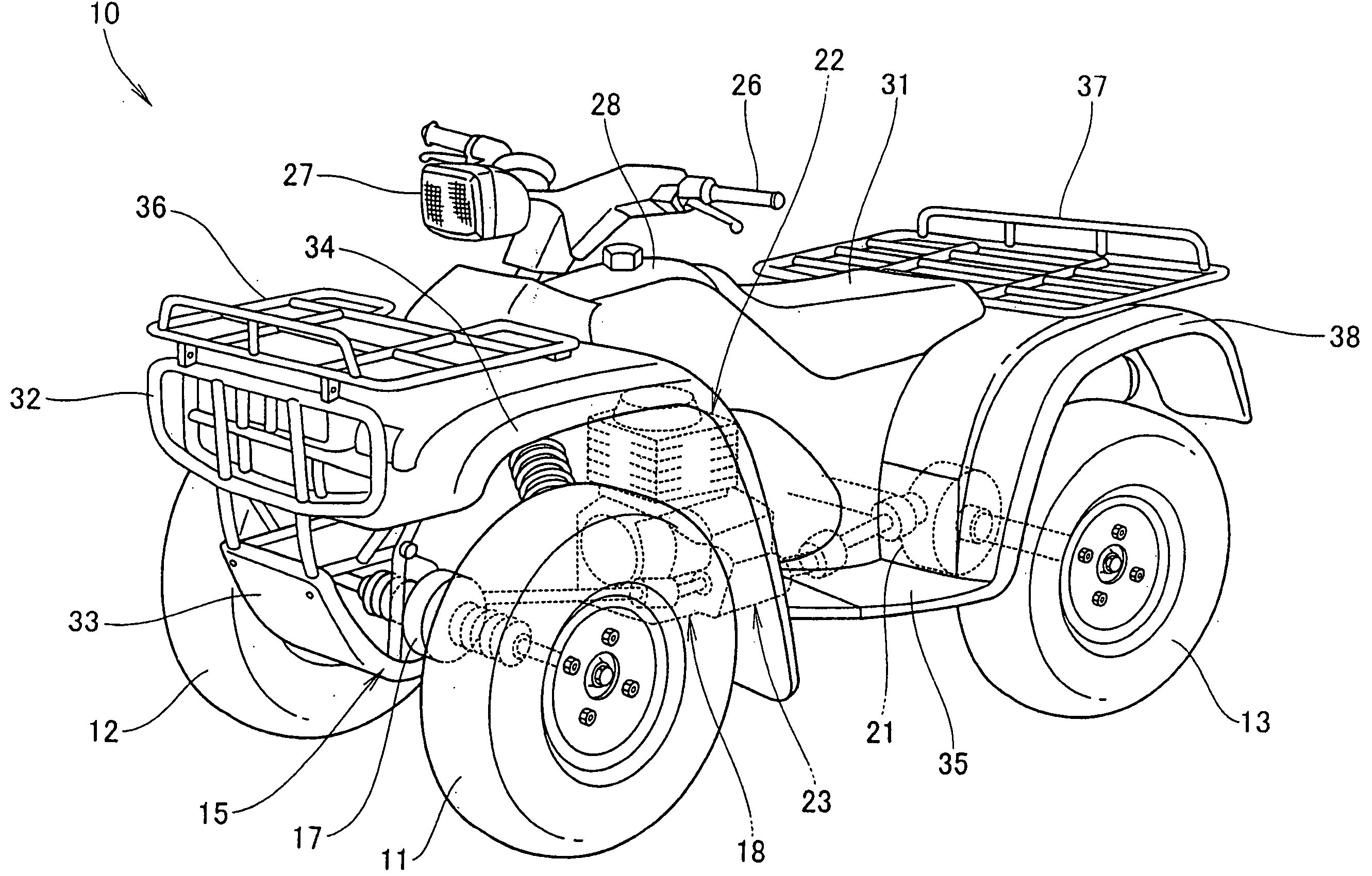
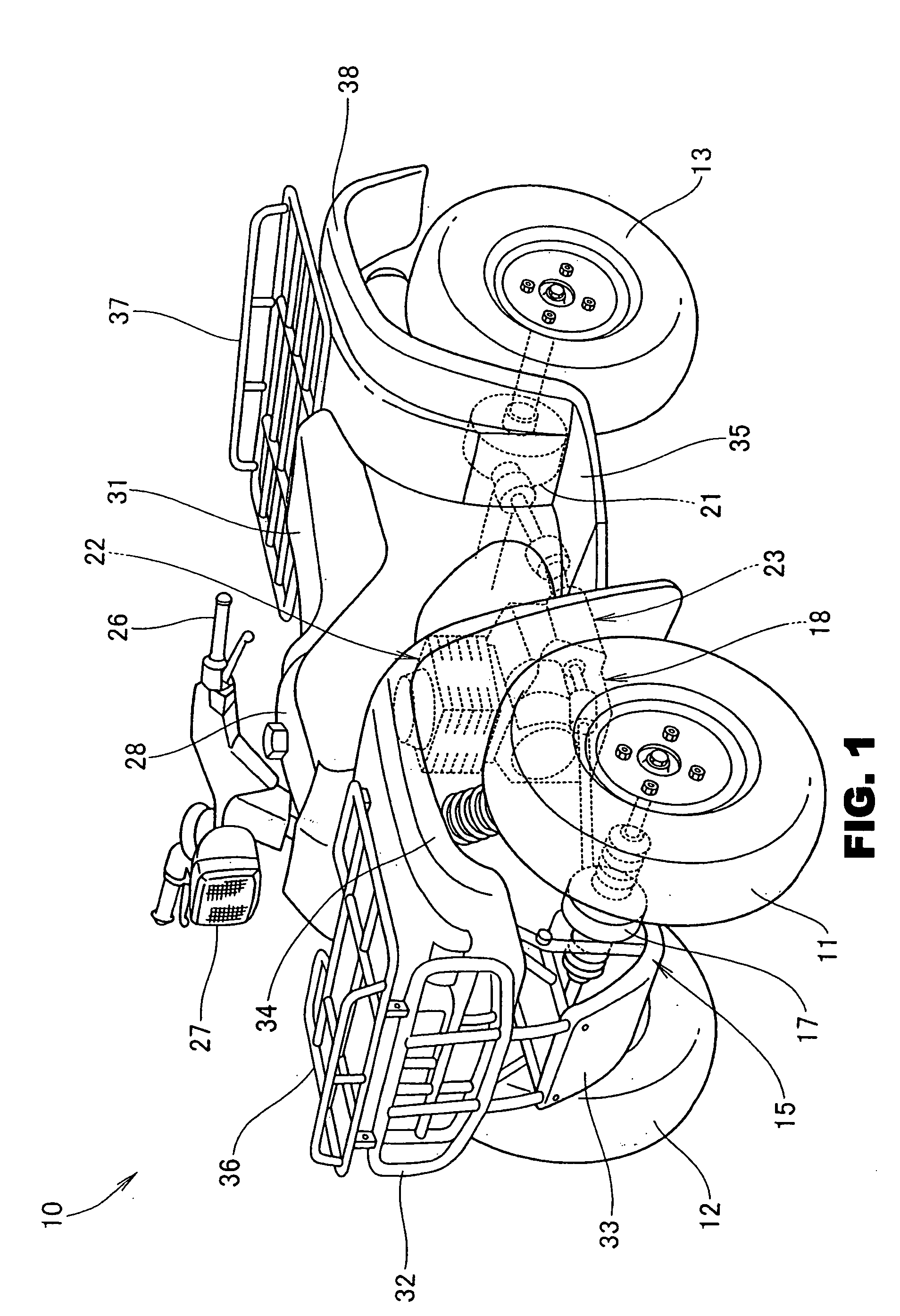
[0064]FIG. 1 is a perspective view of an ATV adopting a vehicle body frame structure according to the present invention, in which the ATV 10 is a vehicle having a structure in which left and right front wheels 11, 12 and left and right rear wheels 13, 14 (only reference numeral 13 on the viewer's side is shown) are supported by suspension arms (not shown) vertically movably mounted to a vehicle body frame 15, the front wheels 11, 12 are connected to a power unit 18 at a roughly central position of the vehicle body through a front speed reduction gear 17, the rear wheels 13, 14 are connected to the power unit 18 through a rear speed reduction gear 21, and the front wheels 11, 12 are steered by a steering handle 26 through a steering shaft (not shown).

[0065] The power unit 18 is composed of an engine 22, and a transmission 23 connected to an output shaft of the engin...


PUM


Abstract

A vehicle body frame structure for an all-terrain vehicle having at least a front wheel, and including a first frame assembly and a second frame assembly. The first frame assembly includes an arm support portion and a steering shaft support portion located at a front portion of the vehicle body frame structure, for steering the front wheel. The second frame assembly is bisected from the first frame assembly; and the vehicle body frame structure also includes a suspension arm vertically swingably supported by the arm support portion.

Description

FIELD OF THE INVENTION [0001] The present invention relates to a vehicle body frame structure for an all-terrain vehicle such as a buggy. BACKGROUND OF THE INVENTION [0002] In general, a vehicle body frame structure for an all-terrain vehicle (hereinafter referred to as an “ATV”), wherein the vehicle body frame is of a bisected structure has been known. [0003] Such is disclosed, for instance, in Japanese Patent Laid-open No. Sho 63-170176. FIG. 2 of Japanese Patent Laid-open No. Sho 63-170176 will be described referring to FIG. 8 below. [0004]FIG. 8 is a perspective view of a conventional vehicle body frame structure for an ATV, in which a vehicle body frame 201 is composed of an upper vehicle body frame 202, a lower vehicle body frame 203 connected to a lower portion of the upper vehicle body frame 202, and cushion brackets 204 (only one on one side is shown) connected respectively to front portions of the upper vehicle body frame 202 and the lower vehicle body frame 203. [0005] Th...

Claims


Application Information

Patent Timeline
IPC IPC(8): B62K5/00B62K5/01
CPCB62J17/00B62K2005/001B62K5/01
Inventor TAKESHIMA, MASAOASAO, KOSUKETAKAHASHI, SHINJITSURUTA, YUICHIRO
Owner HONDA MOTOR CO LTD
Why Eureka
Try Eureka