Cable holder

a technology of cable holder and holder, which is applied in the direction of cable insertion sealing means, electrical equipment, cable fittings, etc., can solve the problems of time-consuming and dangerous procedures, electrical tape use in making repairs, and inability to meet the needs of use, etc., to achieve convenient use, economic effect, and convenient us

Inactive Publication Date: 2015-05-28
NEXT WAVE DESIGN
View PDF11 Cites 24 Cited by
  • Summary
  • Abstract
  • Description
  • Claims
  • Application Information

AI Technical Summary

Benefits of technology

[0024]It will also be appreciated from the above that the cable holder of the invention will cover, insulate, support and weat...

Problems solved by technology

It has often been a problem in relation to electrical cables to prevent bare metal conductors from contacting each other when doing routine electrical repair work such as connecting adjacent ends of metal together or conductors.
Also electrocution may occur if a damaged electrical cable is touched.
However the use of electrical tape in making repairs is dangerous because it may loosen or deteriorate over the passage of time.
This procedure is time consuming and also dangerous because the grub screws may loosen over the passage...

Method used


Image

  • Cable holder
  • Cable holder
  • Cable holder

Examples


first embodiment

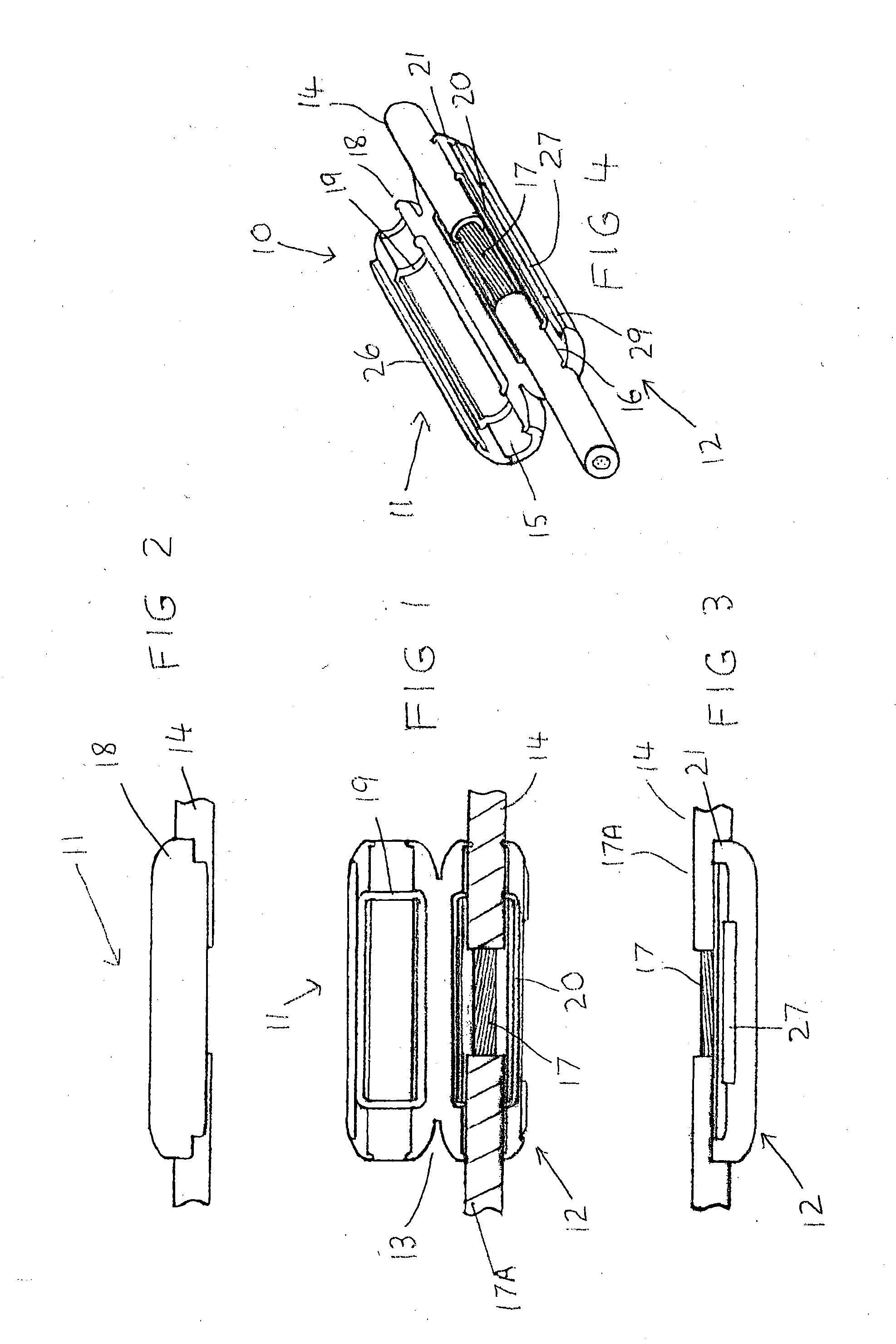
[0031]FIG. 1 is a plan view of a cable holder of the invention;

[0032]FIG. 2 is a side view of a top component of the cable holder shown in FIG. 1 enclosing the cable;

[0033]FIG. 3 is a side view of a bottom component of the cable holder shown in FIG. 1 enclosing the cable;

[0034]FIG. 4 is a perspective view of the cable holder shown in FIG. 1;

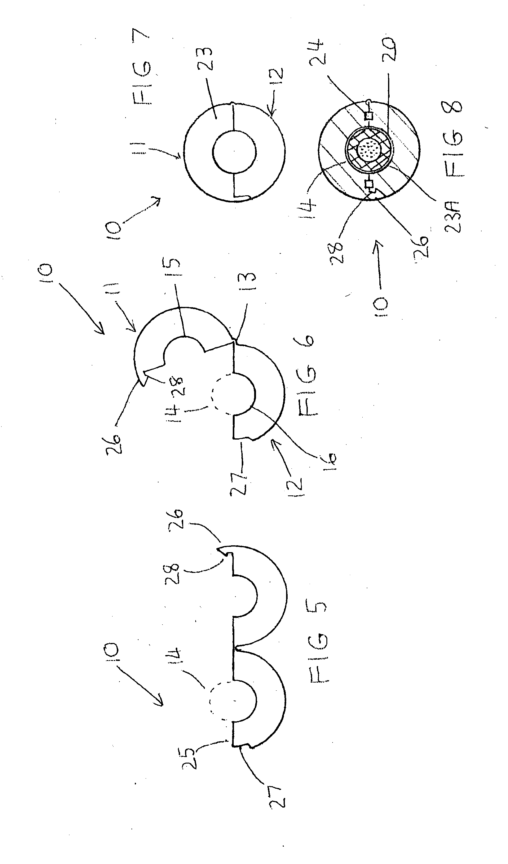
[0035]FIG. 5 is an end view of the cable holder shown in FIG. 1 in a fully open position;

[0036]FIG. 6 is a similar view of the cable holder shown in FIG. 5 in a partially open position;

[0037]FIG. 7 is a similar view of the cable holder shown in FIG. 5 in a fully closed position;

[0038]FIG. 8 is a transverse sectional view of the cable holder shown in FIG. 7;

[0039]FIG. 9 is a perspective external view of the cable holder shown in FIG. 1;

[0040]FIG. 10 is a perspective internal view of the cable holder shown in FIG. 1;

second embodiment

[0041]FIG. 11 is a plan view of a cable holder of the invention;

[0042]FIG. 12 is a longitudinal section through the cable holder of FIG. 11;

[0043]FIG. 13 is a side view of the cable holder shown in FIG. 11;

[0044]FIG. 14 is an end view of the cable holder shown in FIG. 11;

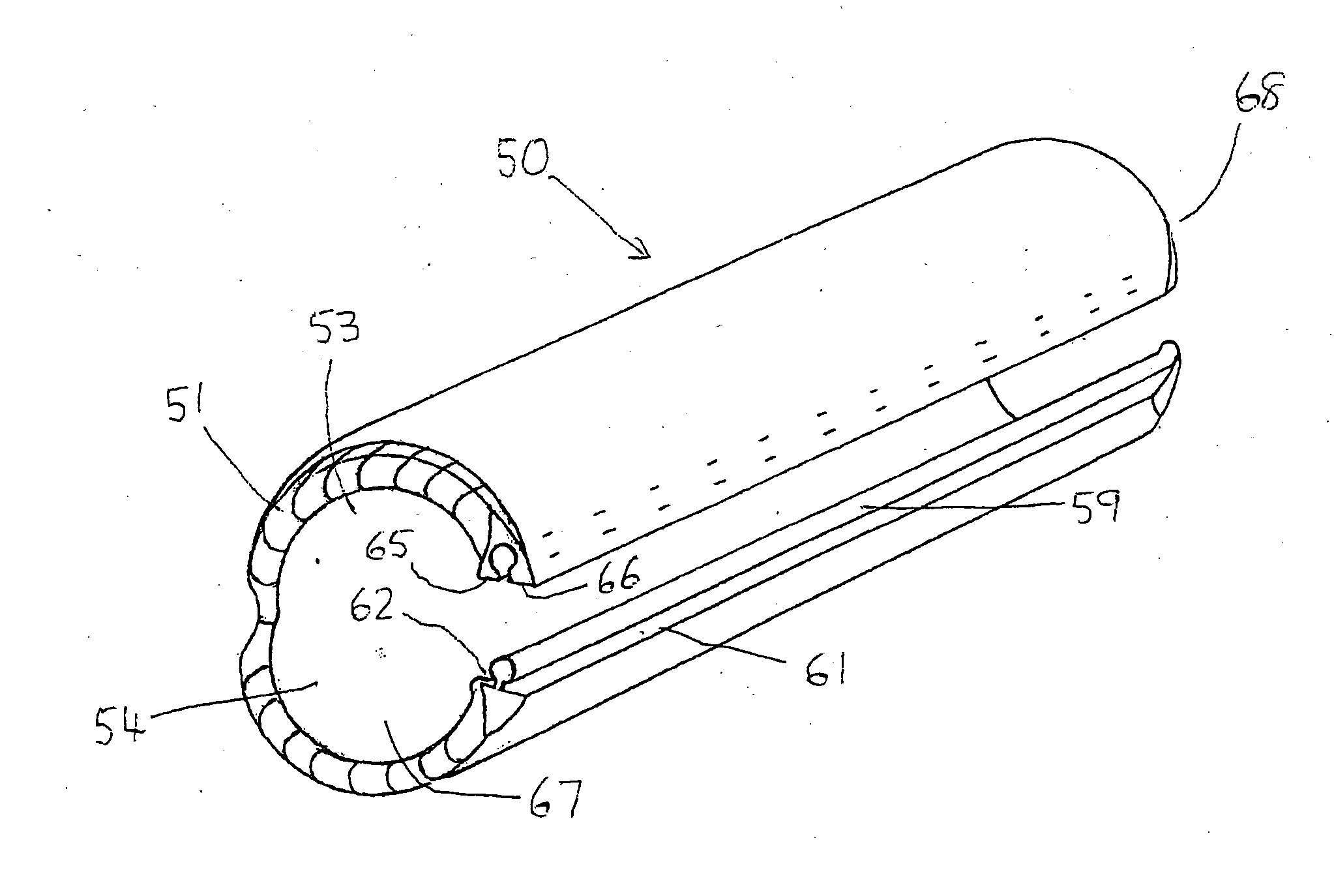
[0045]FIG. 15 is a perspective internal view of the cable holder shown in FIG. 12;

[0046]FIG. 16 is a perspective internal view of the cable holder shown in FIG. 11;

[0047]FIG. 17 is a perspective view of a male component of the cable holder shown in FIG. 11,

[0048]FIG. 18 is a perspective view of the male component shown in FIG. 17;

[0049]FIG. 19 is an end view of the male component shown in FIGS. 17-18;

[0050]FIG. 20 is a perspective view of the female component of the cable holder shown in FIG. 11;

[0051]FIG. 21 is a perspective view of the female component shown in FIG. 20;

[0052]FIG. 22 is an end view of the female component shown in FIG. 20;

[0053]FIG. 23 is a perspective view of the cable holder of this embodiment;

[0...


PUM


Abstract

A cable holder useful for holding a single insulated cable assembly or a multiplicity of insulated cable assemblies wherein the cable holder is formed by a pair of components attached to or integral with each other so as to form a sheath or sleeve for containing the cable assembly or cable assemblies. Adjacent metal ends of the adjoining cable parts are interconnected by a metal joint.

Description

FIELD OF THE INVENTION[0001]This invention relates to a cable holder for use in holding or retaining one or more electrical cables wherein the cable holder is an insulating sleeve which insulates a bare metal joint formed by metal ends of adjacent insulated cables.BACKGROUND OF THE INVENTION[0002]It has often been a problem in relation to electrical cables to prevent bare metal conductors from contacting each other when doing routine electrical repair work such as connecting adjacent ends of metal together or conductors. It will be appreciated that electrical cables or wires when damaged are fire hazards. Also electrocution may occur if a damaged electrical cable is touched. If electrical cable repairs are contemplated it is necessary to switch off all power sources such as by going to the circuit breaker or fuse box. It is then usual to cut an insulation layer off the metal cable so that each cable or conductor can be examined. If damage has occurred it is the usual practice to sep...

Claims


Application Information

Patent Timeline
IPC IPC(8): H02G15/113H02G1/14H02G15/117
CPCH02G15/113H02G1/14H02G15/117H02G1/16H02G15/013
Inventor WEBB, ANTHONY PHILIP
Owner NEXT WAVE DESIGN
Why Eureka
Try Eureka