
Building wiring system, components and methods

a wiring system and building technology, applied in the direction of coupling device connection, coupling device engagement/disengagement, electrical equipment, etc., can solve the problems of increasing the material cost of installing outlets and control modules, labor-intensive and time-consuming cable/wire installation process, and labor-intensive installation of pigtails, so as to save labor and cost, the effect of saving costs

Inactive Publication Date: 2017-10-31
JABLONSKI JEROME
View PDF13 Cites 0 Cited by
  • Summary
  • Abstract
  • Description
  • Claims
  • Application Information

AI Technical Summary

Benefits of technology

The present invention provides a new way to wire electrical devices. It is designed to be efficient, labor-saving and safer. It also reduces the risk of fire and shock to the installer and makes the installation process easier, especially for junction or component devices such as switches and outlets.

Problems solved by technology

Cable / wire installation is a labor intensive and time consuming process that may require electricians of various skill levels.
The installation of pigtails is labor intensive and increases the material costs of installing outlets and control modules.
In prior systems for installation of cables / wires, the termination phase of the installation process is the most time consuming portion of the process, and hence, the most costly.

Method used


Image

  • Building wiring system, components and methods
  • Building wiring system, components and methods
  • Building wiring system, components and methods

Examples


Embodiment Construction

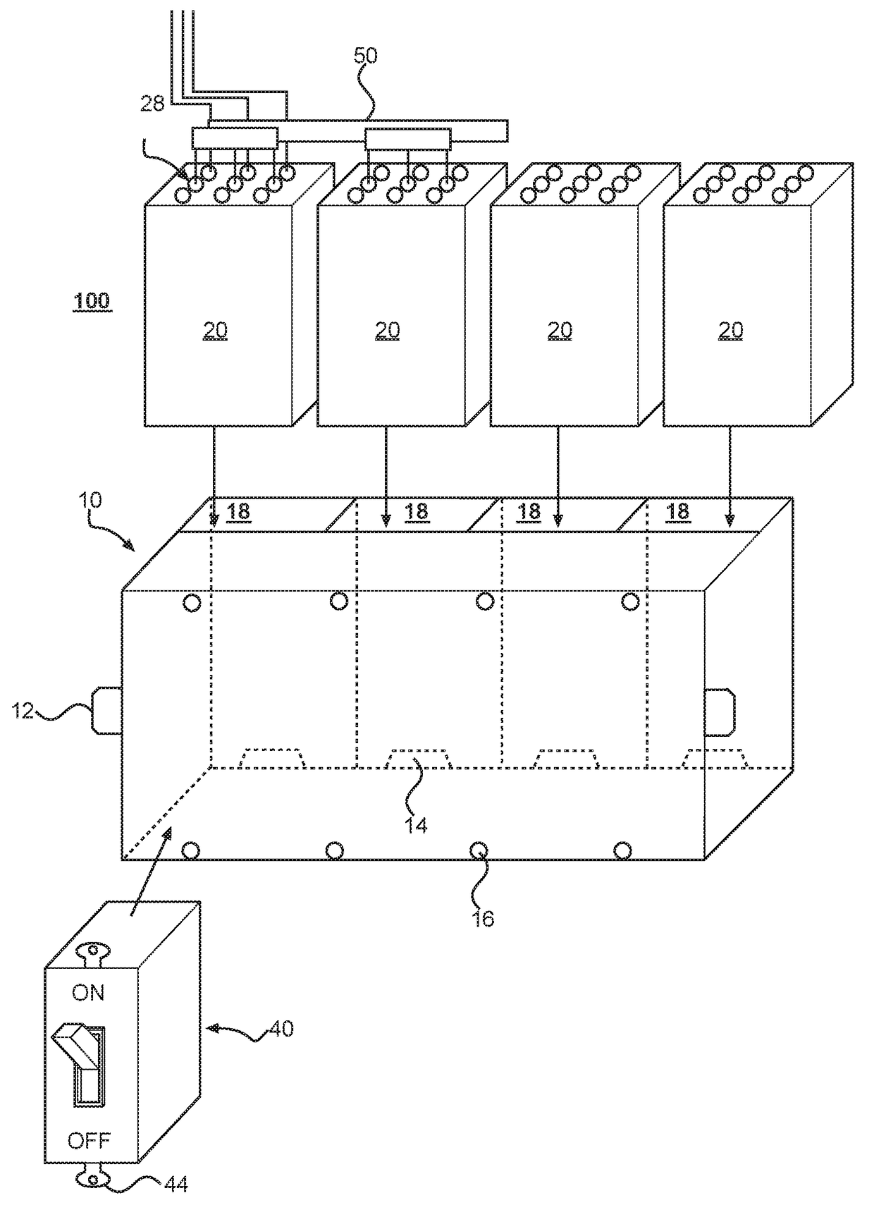
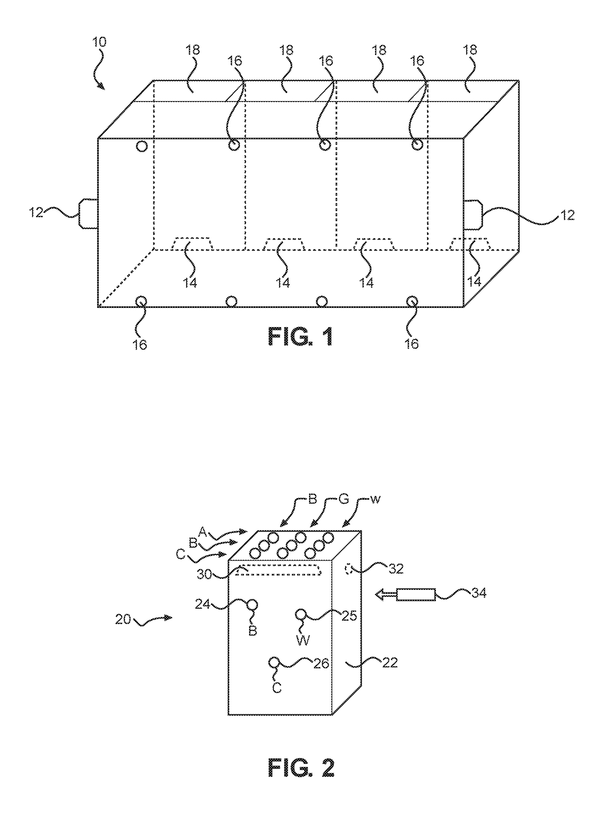
[0033]As discussed above, embodiments of the present invention relate to a building wiring systems, components and methods and more particularly to an approach to wiring a building using the components described below to improve the efficiency of installation while reducing fire hazards and reducing possible shock.

[0034]Generally speaking, metal or molded electrical boxes designed for nail or screw attachment to wooden beams or studs are well known in the construction industry. They come in rectangular shapes for one gang to many gangs; they are also available as round boxes.

[0035]Electrical boxes have been produced for many years in a variety of shapes and dimensions to accommodate various electrical devices such as switches, connectors and receptacles. The electrical boxes require a suitable mounting member for coupling the electrical device to the box. Electrical boxes have a tab or flange with a threaded hole for receiving mounting screws for mounting the electrical device direc...


PUM


Abstract

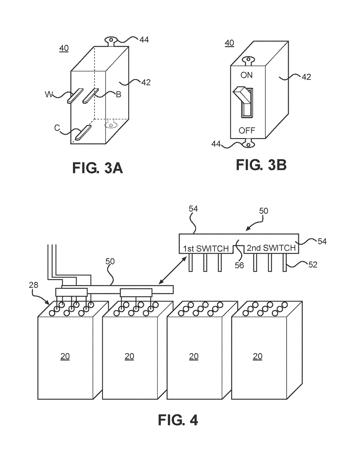
The building electrical wiring system includes a component box to attach to a wall frame, and a current plate configured to be mounted at a back of the component box having a plurality of receiving slots corresponding respectively to hot, neutral and ground. A component device, such as a switch, includes internal component circuitry terminating in a plurality of conductor stems to insert into a respective receiving slot of the current plate. An electrical jumper bar includes an insulated conductor extending between opposite ends which include a respective prong for each conductive path and configured to electrically couple the current plate to another current plate associated with another component device.

Description

COPYRIGHT NOTICE[0001]A portion of the disclosure of this patent document contains material which is subject to copyright protection. The copyright owner has no objection to the facsimile reproduction by anyone of the patent document or the patent disclosure, as it appears in the Patent and Trademark Office patent file or records, but otherwise reserves all copyright rights whatsoever. 37 CFR 1.71(d).BACKGROUND OF THE INVENTION[0002]The following includes information that may be useful in understanding the present invention(s). It is not an admission that any of the information provided herein is prior art, or material, to the presently described or claimed inventions, or that any publication or document that is specifically or implicitly referenced is prior art.1. Field of the Invention[0003]The present invention relates generally to the field of building wiring and more specifically relates to a building wiring system, components and method.2. Description of the Related Art[0004]B...

Claims


Application Information

Patent Timeline
IPC IPC(8): H01R13/60H01R25/16H01R43/26
CPCH01R25/162H01R25/165H01R43/26H01R9/2466H02G3/081H02G3/12
Inventor JABLONSKI, JEROME
Owner JABLONSKI JEROME
Learn More