Apparatus for lap seaming floor coverings

a technology of lap seaming and floor covering, which is applied in the direction of sawing apparatus, metal working apparatus, constructions, etc., can solve the problems of creating non-uniform seams between tiles, inconvenient use of tools to make arcuate cuts in tiles, and conventional tools are not typically intended to make long continuous and uniform seams

Inactive Publication Date: 2007-10-09
VANDEN HEUVEL RICK J +1
View PDF32 Cites 0 Cited by
  • Summary
  • Abstract
  • Description
  • Claims
  • Application Information

AI Technical Summary

Benefits of technology

[0018]The apparatus and method are particularly suited for vinyl and linoleum tile floor coverings. Each floor covering is formed by a batch of like-shaped tiles with a specific surface color or style. The apparatus allows the tiles to be arranged and secured to the floor in an intended array before they are cut to form the seam where they meet. Each tile is placed and secured at a position where it is ultimately located when the floor pattern is complete. The apparatus cuts the entire array of overlapping tiles in a single stroke or pass to produce a seam from one end of the array to the other. Cutting the entire array of tiles in this continuous pass creates a uniform seam between the tiles with an attractive and professional appearance. Transition pieces are not required to cover the seam.
[0019]The apparatus and method of the present invention are time and labor efficient. Vinyl and linoleum tiles are easily cut in both straight and arcuate manners. The tiles are not scored and broken to fit them together. Templates are not needed, and time is not wasted aligning small sections of cuts. Discontinuities between such sections are avoided. The imprecision, fatigue and safety hazards associated with conventional hand tools and torches are avoided. Nicks and gouges in the edges of the floor coverings along the seam, and unsightly score marks on the surface of the floor coverings are avoided. The resulting arcuate seam is formed by two flushly abutting floor coverings or produces a constant gap between the floor coverings to produce an attractive and professional appearance.
[0020]The apparatus continuously heats and cuts through the overlapping tile floor coverings. The apparatus moves at a constant desired rate of speed so that each tile is heated about the same amount to a consistent desired temperature prior to and while being cut. The blade biasing mechanism and drive mechanism are set to produce a constant amount of cutting force between the blade and floor coverings and a constant cutting speed during the entire cut. The relatively slow speed of the apparatus enables the heating units to be set at a power level that will consistently heat the tiles to the desired temperature without scorching or discoloring the tiles. The intensity and danger of a propane flame is avoided. The repetition and misalignments associated with moving a template or heat shield along the cut line is also avoided.
[0021]The present invention forms a safe and attractive uniform seam that does not require transition cap. The cut edges of the adjacent floor coverings abut along the seam to produce a physically and aesthetically smooth transition from one floor covering to the other. The upper surfaces of the different floor coverings are planar and there is little or no gap between the floor coverings to cause a person to trip, or into which dirt and debris can collect and cause the tiles to lift up over time. The seam provides a smooth transition between the floor coverings that is safe to walk over and that gives the overall design a clean unobstructed appearance.

Problems solved by technology

While these tools are readily used to cut like-shaped tiles to the same shape or dimensions, the tools are not readily used to make arcuate cuts in the tiles, particularly after they are secured to or positioned on the floor.
Cutting individual pieces of floor covering tiles and then aligning them on the floor tends to create a non-uniform seam between the tiles.
Conventional tools are not typically intended to make long continuous and uniform seams between two adjacent floor coverings, particularly when the floor covering is positioned over and secured to the floor in an array forming the intended design.
These anomalies produce a shoddy and unprofessional appearance that can require large sections of the floor coverings to be removed, replaced and recut to achieve an acceptable seam.
Conventional floor covering techniques and tools are time consuming to use and require a significant amount of manual labor.
The density and durability of floor covering such as vinyl and linoleum tiles make them difficult to cut, particularly in an arcuate manner.
Scoring and breaking tile along a score line is difficult or impossible to do once the tile is placed over and secured to the floor.
Each cut takes time and can result in an unsightly score mark on the surface of the tile if the tool ventures off the intended cut line.
If the tool is not properly guided, the blade can jump off line and gouge the floor coverings, damage the template, or injure the worker.
Still, the upper floor covering will be exposed to the flame if the template is not flush aligned with the cut line.
In addition, the lower floor covering is not protected by the template and will be exposed to the flame if it is not covered by the upper covering.
During the long and repetitive process of intermittently heating and cutting small sections of floor covering, workers are often hurt and the floor covering is often inadvertently scorched or otherwise discolored.
The end result is a more costly project and an unprofessional looking seam.
This lack of uniformity of force, speed and temperature can cause the blade to cut all the way through one section of the tile and only partially through another.
There is also little or no way to ensure that the cut has gone completely through both overlapping floor coverings.
Workers can make another possibly unnecessary stroke and risk inadvertently nicking or gouging the template, inadvertently scoring the surface of the floor coverings or hurting themselves.
Although transition caps or covers can be used to cover an unattractive seam between two adjacent floor coverings as in FIG. 1F, these caps are not always desirable.
These caps create a ridge that can cause a person to trip and injure themself.
This problem is accentuated if the cap becomes loose over time and begins to lift up off the floor.
The transition cap also forms a break or discontinuity in the floor design and can adversely impact the appearance of the design.
Placing a transition cap over a seam in the middle of a room or along a walkway where a person would not normally expect to find such a cap is not always desirable.

Method used


Image

  • Apparatus for lap seaming floor coverings
  • Apparatus for lap seaming floor coverings
  • Apparatus for lap seaming floor coverings

Examples


second embodiment

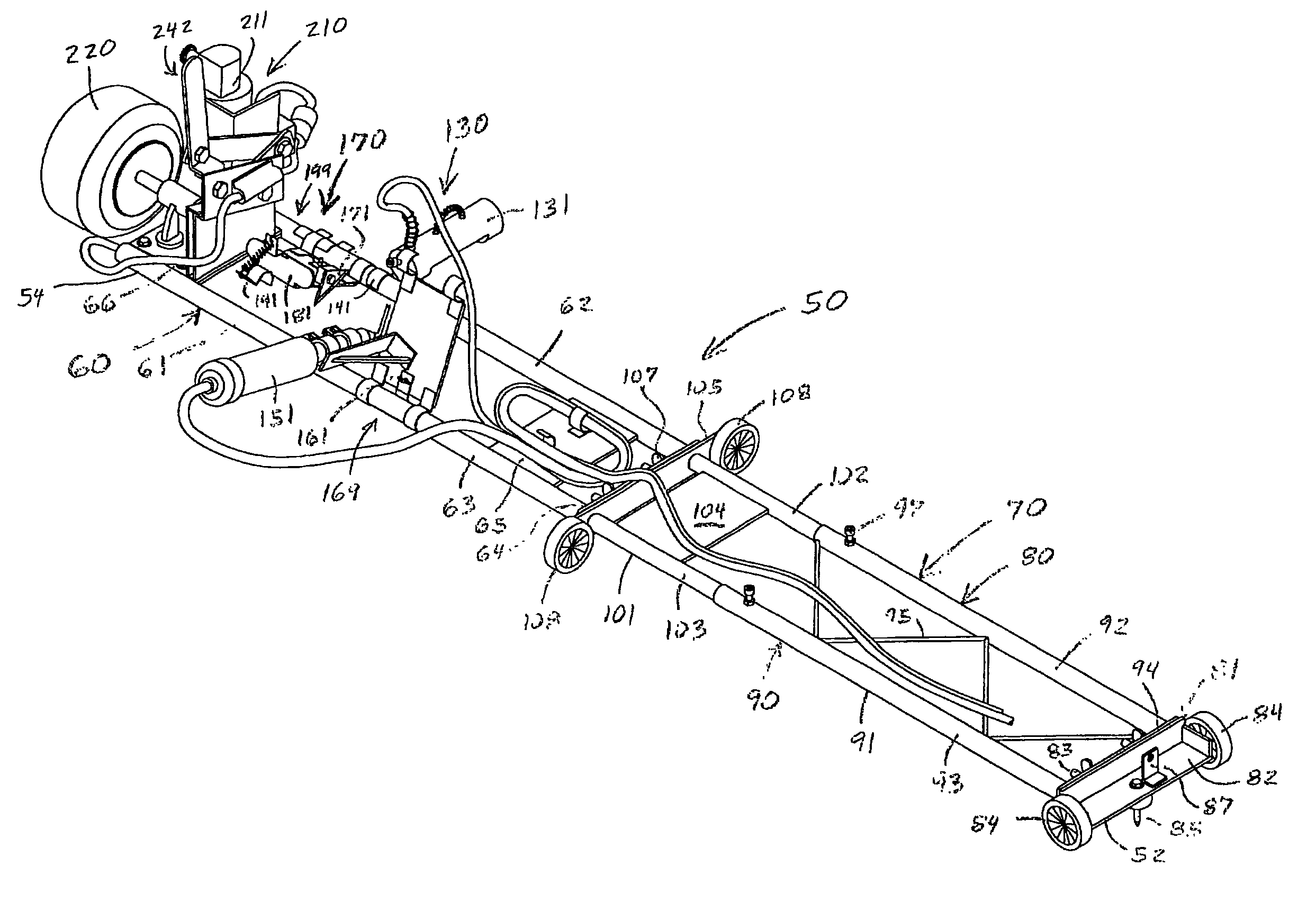
[0065]The marking and lap seaming apparatus 50 has a working section 60 with a frame 61 that supports and connects its various working components discussed below. The frame 61 is robustly designed to support the weight of these various components and is preferably made of metal. The frame 61 includes two parallel, spaced apart tubes 62 and 63 that are rigidly joined by a perpendicular cross plate 64 and two mounting brackets 65 and 66. The tubes 62 and 63 are preferably spaced about six inches apart. The support tubes 62 and 63 and mounting brackets 65 and 66 are aligned substantially parallel to and about an inch above the surface 12 of the floor 10. The forward tube 62 is preferably marked with indicia (not shown) for positioning the working components as discussed below. In the embodiment of the apparatus 50 shown in FIG. 2, the frame 61 and its support tubes 62 and 63 are about three feet long. In the apparatus 50 shown in FIG. 5, the frame 61 and its support tubes 62 and 63 are...

first embodiment

[0067]the alignment mechanism 70 is shown in FIGS. 2 and 3. In this embodiment, the alignment mechanism 70 takes the form of a rotatably anchored, telescoping assembly 80 that includes anchor and telescoping assemblies 81 and 90. The anchor assembly 81 has an L-shaped mounting plate 82 with a pair of spaced coupling bolts and wing nuts 83 for rigidly connecting the anchor assembly 81 to the telescoping section 90. A pair of wheels 84 are mounted to the sides of the mounting plate 82. A vertically oriented pivot pin or anchoring screw 85 is located at the middle of the plate 82. The axles of the wheels 84 are linearly aligned with each other and the axis of the pivot pin 85. The pivot pin 85 is aligned with and anchored or otherwise rigidly secured to the floor 10 at reference point 55. The pivot pin 85 is pivotally or rotatably connected to the middle of the mounting plate 82 to allow the anchor assembly 81 to pivot or rotate about the reference point 55 and pivot pin. An alignment ...


PUM

PropertyMeasurementUnit
temperatureaaaaaaaaaa
weightaaaaaaaaaa

Abstract

The present invention pertains to an apparatus for continuously cutting different floor coverings to form a uniform seam between them. The apparatus is particularly suited for vinyl and linoleum tile floor coverings. The apparatus is secured to a floor at a reference point or along a reference path. The different floor coverings are each placed on one of the separate areas so that they each overlap and continuously cover a border mark. Cutting and heating devices are secured to the apparatus substantially the same distance from the reference point or path. A drive mechanism propels the apparatus at a desired rate of speed to move the cutting device along the specific path of travel over the border to continuously heat and cut the overlapping floor coverings to form a uniform lap seam between them.

Description

CROSS REFERENCE TO RELATED APPLICATION[0001]This application is a Continuation of U.S. patent application Ser. No. 10 / 154,781, filed May 24, 2002 now abandoned.TECHNICAL FIELD OF THE INVENTION[0002]The present invention relates to an apparatus and method for marking a floor by securing the apparatus at a reference point or path so as to move along a desired path of travel to form a border mark, laying floor covering in an overlapping manner over the border mark, and moving the apparatus along the path of travel to continuously cut the floor coverings along the border mark to form a uniform seam between them.BACKGROUND OF THE INVENTION[0003]Floor coverings are widely used as durable and attractive products to cover a floor of a building or one of its individual rooms. The floors are generally flat and made of structurally strong materials such as concrete, plywood, steel and the like. The floors require an attractive floor covering that is more appropriate for the intended living or ...

Claims


Application Information

Patent Timeline
Patent Type & Authority Patents(United States)
IPC IPC(8): B26D7/10
CPCE04F21/0076E04F21/00Y10T83/04Y10T83/293Y10T83/68Y10T83/8789
Inventor VANDEN HEUVEL, RICK J.
Owner VANDEN HEUVEL RICK J
Why Eureka
Try Eureka