
Process for the Production of an Electronic Card having an External Connector and Such an External Connector

Active Publication Date: 2015-05-28
NAGRAVISION SA
View PDF1 Cites 11 Cited by
  • Summary
  • Abstract
  • Description
  • Claims
  • Application Information

AI Technical Summary

Benefits of technology

The invention proposes a process for making electronic cards with external connectors that have secure soldered connections to a module embedded in the card. This process aims to ensure reliable electrical connections between the pads, especially when there are multiple ones. The thickness of the insulating support of the external connector and the positioning of the pads in the card body are dissociated from the internal support. This ensures that the pads are not weakly supported and can be easily detached from the module.

Problems solved by technology

It is clear that such a situation is particularly disadvantageous when the holes are close because of the increased risk of short-circuiting.
Hence, a person skilled in the art will consider the configuration of an electronic card according to FIGS. 3A-3C and 4A-4C of the document DE 197 32 645 very difficult, or indeed practically impossible, to implement.
It will be noted that the application of solder material in the apertures of an adhesive film before this is assembled on the electronic module or card body poses problems of production, since it is not obvious how to hold the solder material in the apertures of the adhesive film until the electronic module is assembled with the card body.

Method used


Image

  • Process for the Production of an Electronic Card having an External Connector and Such an External Connector
  • Process for the Production of an Electronic Card having an External Connector and Such an External Connector
  • Process for the Production of an Electronic Card having an External Connector and Such an External Connector

Examples


first embodiment

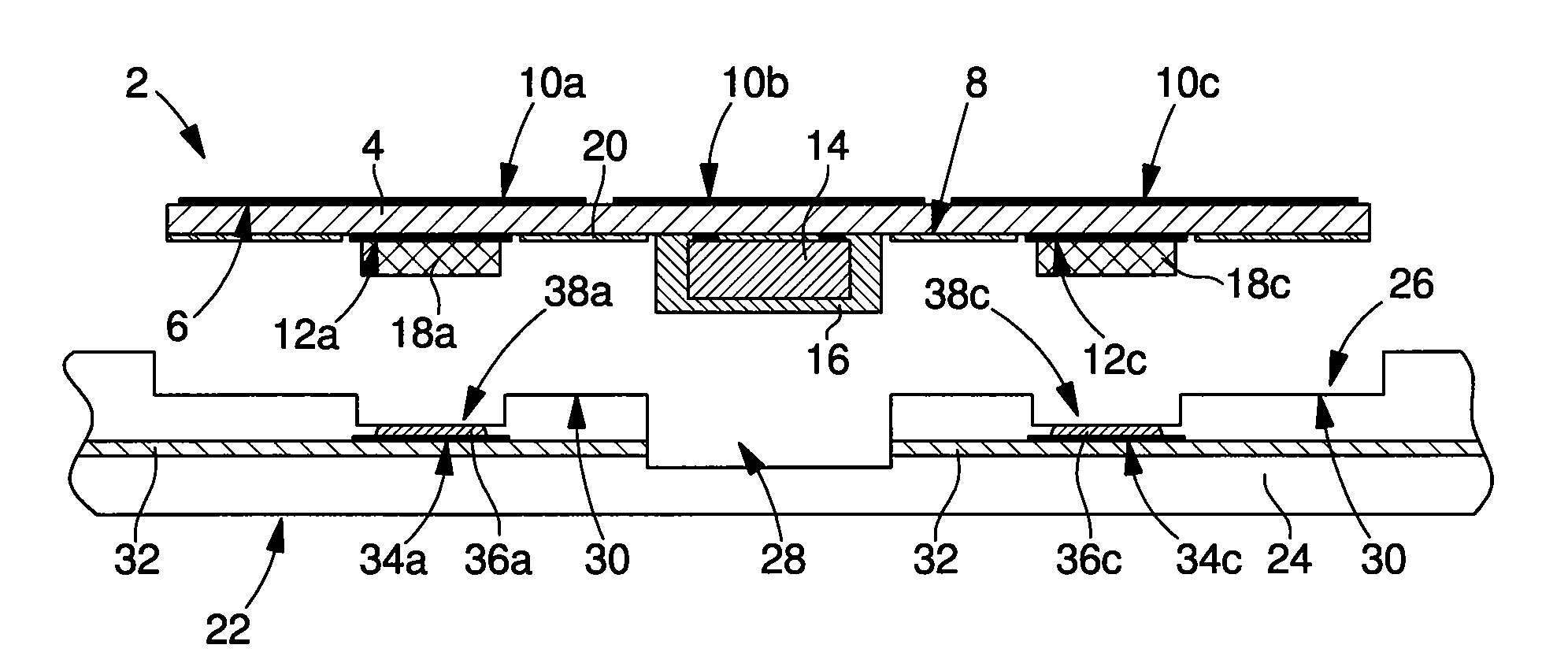
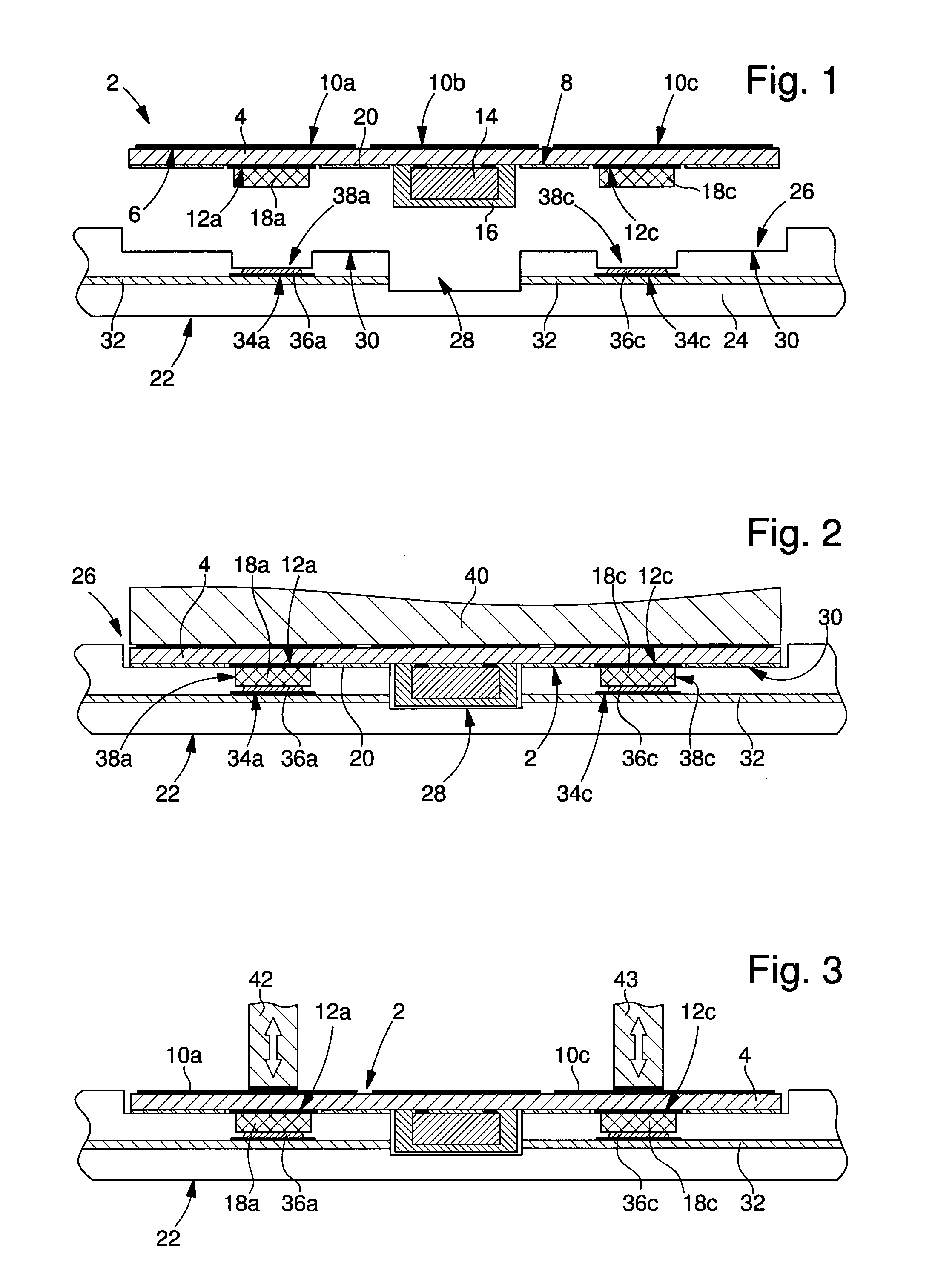
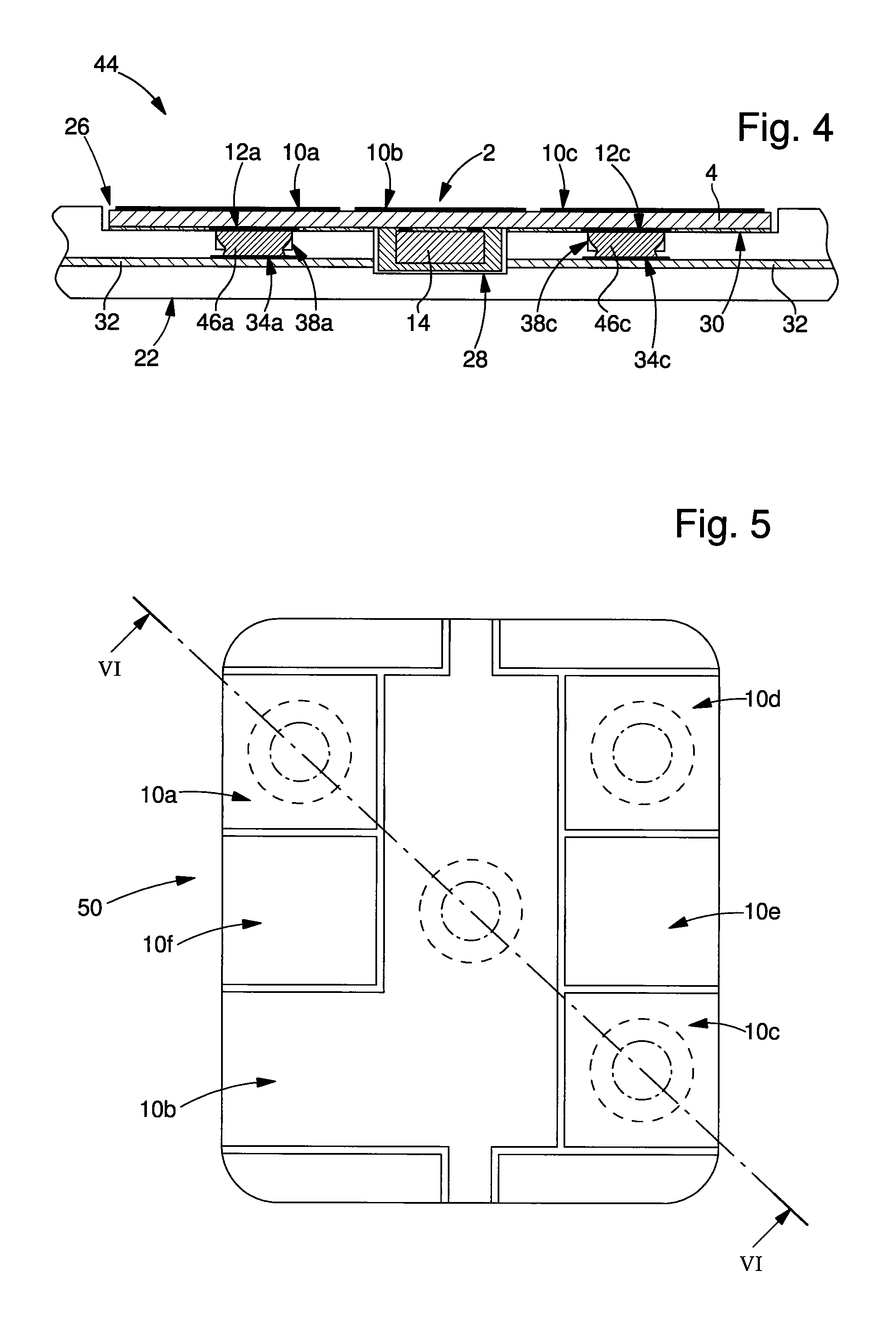
[0027]The production process according to the invention for an electronic card and the resulting card will be described below with the assistance of FIGS. 1 to 4.

[0028]The produced electronic card comprises:[0029]an external connector 2 comprising an insulating support 4 and a plurality of external metal contact pads 10a, 10b, 10c, which are arranged on the outside face 6 of this insulating support;[0030]a card body 22 having a cavity 26 for the external connector 2;[0031]an electronic unit and / or an antenna (not shown in the figures) that is / are incorporated in the card body 22 and electrically connected to a plurality of internal metal contact pads 34a, 34c located in the card body under the cavity 26, i.e. under the general surface defining the base of this cavity, which is formed by the recess 28 and the horizontal surface 30 surrounding this recess.

[0032]The production process generally comprises the following steps:[0033]machining individual cavities 38a and 38c in the card b...

second embodiment

[0051]A second preferred embodiment of the invention and its production process will be described below with the assistance of FIGS. 5 to 8. Some of the elements that have already been described and some of the steps of the production process already explained above will not be explained again in detail below. This second embodiment differs from the first substantially in the arrangement of the external connector, wherein the process of assembly of this external connector on a corresponding card body, in particular the formation of the electrical junctions between them, is similar to that already described.

[0052]The external connector 50 has a plurality of external contact pads 10a to 10f. It comprises an insulating support 4a, which has a plurality of apertures 52a, 52b, 52c (and a fourth that is not visible in the sectional view of FIG. 6) between its outside face 6 and its inside face 8. The apertures of this plurality of apertures are respectively closed by the external pads 10a...


PUM

PropertyMeasurementUnit
Diameteraaaaaaaaaa
Lengthaaaaaaaaaa
Volumeaaaaaaaaaa

Abstract

The invention relates to an external connector for the production of an electronic card comprising an insulating support that defines an outside face and an inside face opposite one another and a plurality of external metal contact pads. This external connector additionally comprises a plurality of metal projections located on the side of the inside face of the insulating support and respectively connected electrically to at least one subassembly of the plurality of external metal contact pads and / or to contact pads linked to an electronic unit, which is arranged on the inside face of the insulating support, wherein these metal projections are intended to be inserted into individual cavities of the body of the electronic card, and metal contact pads linked to an electronic unit inside the card body and / or an antenna incorporated in this card body are located at the base of these cavities. The invention also relates to a process for the production of an electronic card using the aforementioned external connector.

Description

[0001]This is a National Phase Application in the United States of International Patent Application PCT / EP 2013 / 060167 filed May 16, 2013, which claims priority on European Patent Application No. 12168338.7 of May 16, 2012TECHNICAL FIELD[0002]The present invention relates to the field of electronic cards, in particular bank cards, having an electronic unit and / or an antenna incorporated in the body of this card and an external connector arranged in a cavity in this card body, wherein this connector has a plurality of external contact pads arranged on an outside face of an insulating support forming this connector. The electronic unit and / or an antenna is / are electrically connected to a plurality of internal metal contact pads of the card body, which are arranged under the external connector and which are respectively electrically connected to at least one subassembly of the plurality of external contact pads and / or to contact pads linked to a second electronic unit arranged on the i...

Claims


Application Information

Patent Timeline
IPC IPC(8): G06K19/077
CPCG06K19/07775G06K19/07743G06K19/07747G06K19/07754G06K19/07769Y10T29/49018G06K19/077H05K3/303H05K3/368
Inventor DROZ, FRANCOIS
Owner NAGRAVISION SA
Learn More