

Thermal transfer printer
- Summary
- Abstract
- Description
- Claims
- Application Information
AI Technical Summary
Benefits of technology
Problems solved by technology
Method used
Image

Examples
first embodiment
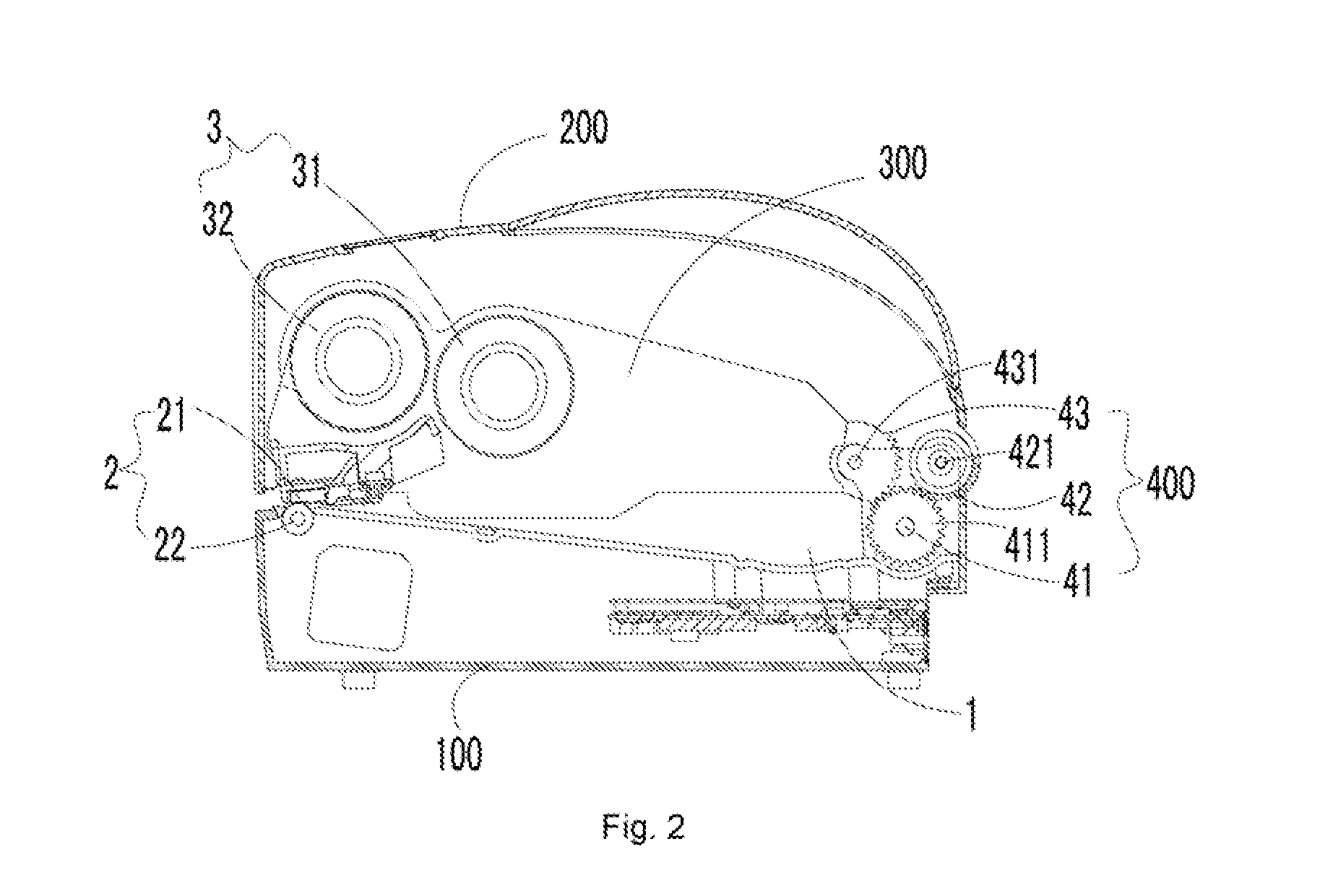
[0077]FIG. 4 is a structure side view of a thermal transfer printer when an upper housing is opened according to the disclosure. The working principle of the linkage mechanism of the thermal transfer printer provided by the embodiment will be introduced below in combination with FIG. 2 and FIG. 4.
[0078]When the operator drives the upper housing 200 to open relative to the base 100, the second gear 42 fixedly connected with the upper housing 200 rotates around the second gear shaft 421 in the clockwise direction of the figures to drive the first gear 41 to rotate around the first gear shaft 411 in the counterclockwise direction of the figures, and the rotation of the first gear 41 drives the third gear 43 to rotate around the third gear shaft 431 in the clockwise direction of the figures. Since the ribbon bracket 300 is fixedly connected with the third gear 43, the carbon bracket 300 rotates around the third gear shaft 431 with the third gear 43 in the clockwise direction of the figu...
second embodiment
[0082]FIG. 5 is a structure side view of a thermal transfer printer when an upper housing is opened according to the disclosure. As shown in FIG. 5, in the embodiment, the driving member of the linkage mechanism 400 is a fourth gear 42′, and the driven member is an annular gear 43′, wherein the base 100 is fixedly connected with an external sleeve 41′, the fourth gear 42′ and the annular gear 43′ are moveably connected with the external sleeve 41′, and the fourth gear 42′ is in engaging transmission with the annular gear 43′.
[0083]FIG. 6 is a structural view of a thermal transfer printer provided with a sleeve base according to the second embodiment of the disclosure, FIG. 7 is a structural view illustrating connection between a driving member of a linkage mechanism and an upper housing of a thermal transfer printer according to the second embodiment of the disclosure, and FIG. 8 is structural view illustrating connection between a driven member of a linkage mechanism and a ribbon b...
PUM
 Abstract
Description
Claims
Application Information