Electronic banding compensation (EBC) of halftone-interaction banding using variable beam delays

a delay delay and halftone technology, applied in the field of printing systems, can solve the problems of periodic density variation in the process direction, inacceptable reprographic printing system, and variation in the density of the marking material fused to the final print medium

Active Publication Date: 2015-05-28
XEROX CORP
View PDF4 Cites 1 Cited by
  • Summary
  • Abstract
  • Description
  • Claims
  • Application Information

AI Technical Summary

Problems solved by technology

Final image quality is affected by various sources of noise and errors in a reprographic system, leading to density variations in the marking material fused to the final print medium.
Certain sources of reprographic system noise and errors cause periodic density variations in the process direction, which are sometimes referred to as “banding” errors.
Other sources of banding errors include gears, pinions, and rollers in charging and development modules; jitter and wobble in imaging modules, as well as photoreceptors and associated drive trains.
If not addressed, such periodic process direction density variations can render a reprographic printing system unacceptable, particularly where the banding errors are visually perceptible.
In practice, it is difficult to completely eliminate the error sources that contribute to banding, or even to reduce them enough to avoid perceptible periodic density variations.

Method used


Image

  • Electronic banding compensation (EBC) of halftone-interaction banding using variable beam delays
  • Electronic banding compensation (EBC) of halftone-interaction banding using variable beam delays
  • Electronic banding compensation (EBC) of halftone-interaction banding using variable beam delays

Examples


Embodiment Construction

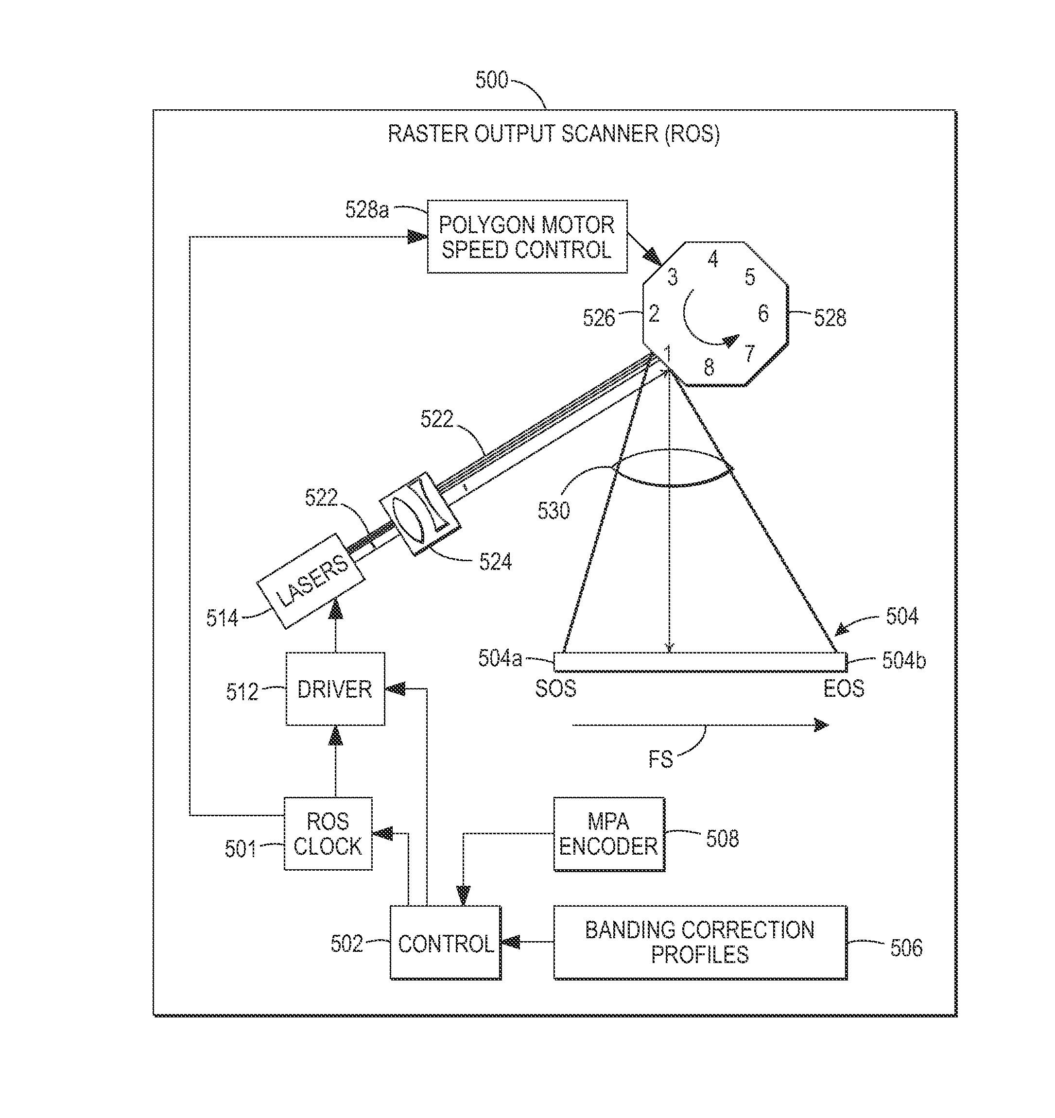
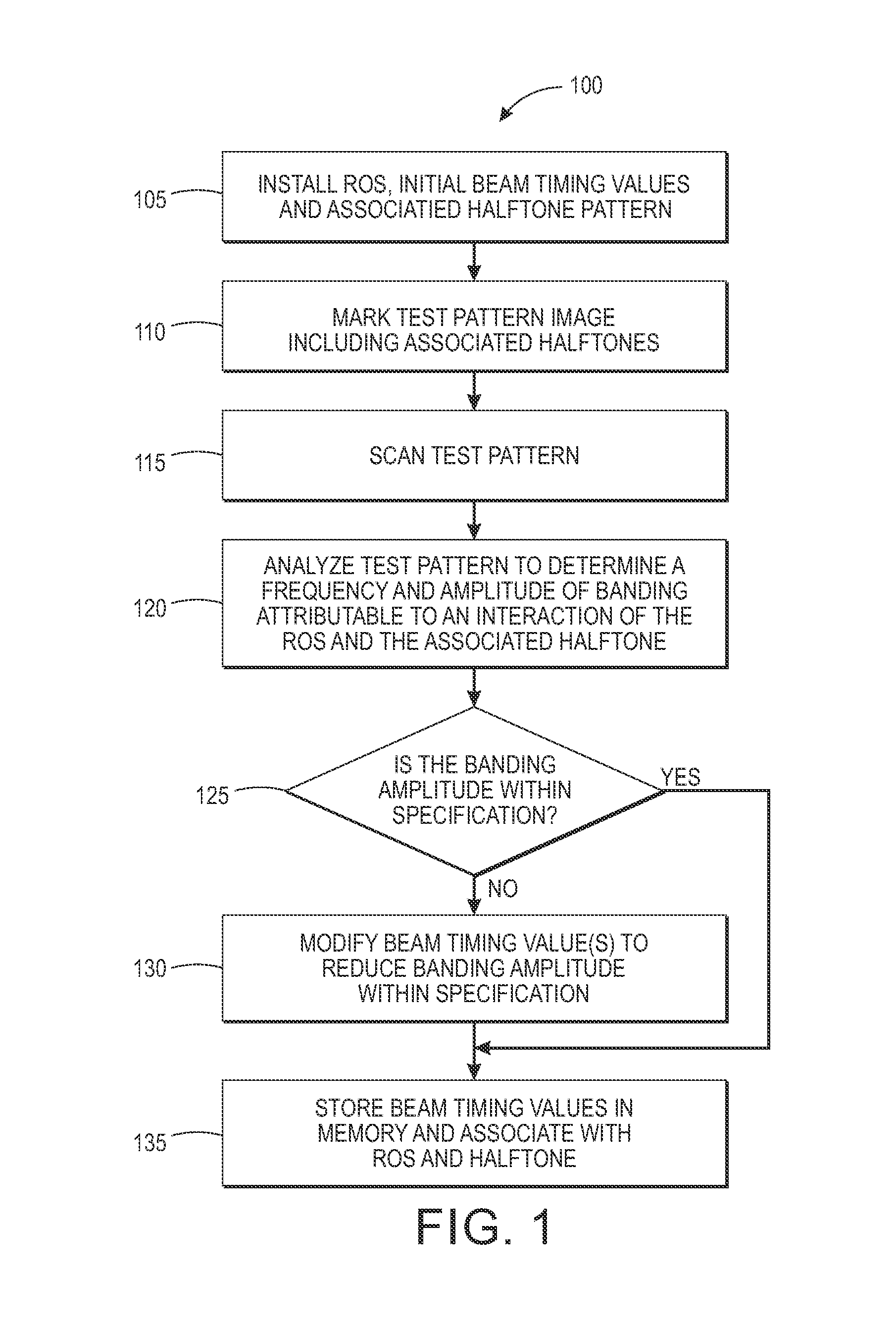
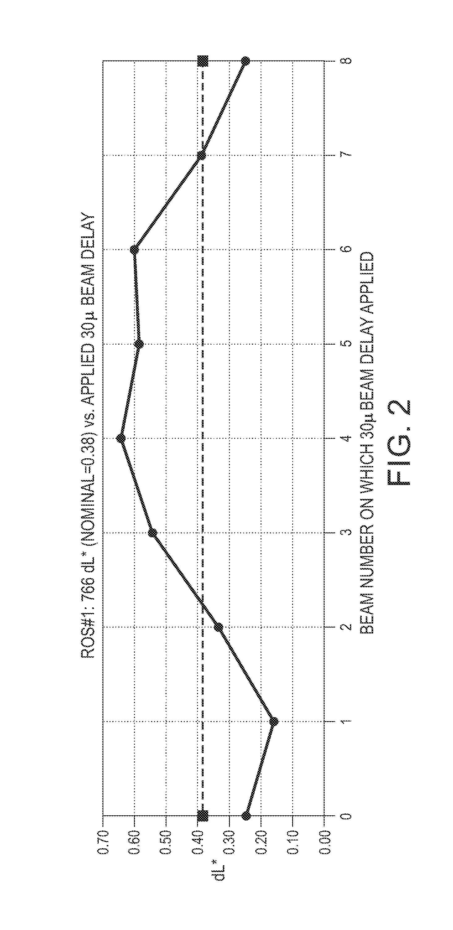
[0025]Provided herein are methods and systems to compensate for banding caused by the interaction of Raster Output Scanner (ROS) variations with a halftoned image. The interaction of ROS variations with a halftoned image can cause an objectionable printed output density variation at a spatial frequency that is visually perceptible. The disclosed method and system provide the use of one or more fast scan beam delays operatively associated with a multibeam ROS as an actuator for a compensation scheme to reduce banding. Examples of a multibeam ROS include, but are not limited to, a VCSEL (Vertical-Cavity Surface-Emitting Laser), and multibeam laser diodes. The fast scan beam delays may be positive or negative to delay or advance, respectively, to a fast scan beam relative to one or more other beams or a nominal value. The provided actuator has enough compensation authority to perform the compensation function. Tests demonstrate the compensation holds for a particular ROS over different...


PUM


Abstract

Disclosed are methods and systems for compensating for process direction banding associated with a document processing system including a ROS. According to one exemplary embodiment, a ROS driver uses a plurality of beam delay / advance values to compensate for banding caused by an interaction of a halftone pattern and process direction density variations associated with the ROS.

Description

CROSS REFERENCE TO RELATED PATENTS AND APPLICATIONS[0001]U.S. patent application Ser. No. 13 / 313,533, filed Dec. 7, 2011, now U.S. Publication No. 2013 / 0148172, published Jun. 13, 2013 by Robert Herloski et al. and entitled “Printing System, Raster Output Scanner, and Method with Electronic Banding Compensation Using Facet-Dependent Smile Correction” and U.S. patent application Ser. No. 13 / 334,251, filed Dec. 22, 2011 (now U.S. Publication No. 2013 / 0163055, published Jun. 27, 2013) by Robert Herloski et al. and entitled “Process for Creating Facet-Specific Electronic Banding Compensation Profiles for Raster Output Scanners”, are incorporated herein by reference in their entirety.BACKGROUND[0002]The present exemplary embodiments relate to printing systems with raster output scanner (ROS) apparatuses and to techniques for mitigating banding errors. Reprographic printing systems are used to create marked images on paper or other markable media, and improving the quality of the produced...

Claims


Application Information

Patent Timeline
Patent Type & Authority Applications(United States)
IPC IPC(8): B41J2/47H04N1/00
CPCH04N1/00015B41J2/471B41J2/473G06K15/1257G06K15/027H04N1/506H04N1/405H04N1/06H04N1/113H04N1/1911H04N1/29H04N1/40
Inventor HERLOSKI, ROBERT PAUL
Owner XEROX CORP
Why Eureka
Try Eureka