Eureka AIR delivers breakthrough ideas for toughest innovation challenges, trusted by R&D personnel around the world.

Image Forming Apparatus

Active Publication Date: 2015-05-28
BROTHER KOGYO KK
View PDF0 Cites 0 Cited by
  • Summary
  • Abstract
  • Description
  • Claims
  • Application Information

AI Technical Summary

Benefits of technology

The present invention provides an image forming apparatus that can protect the image forming unit from liquid damage, even if the apparatus is exposed to liquid.

Problems solved by technology

If the liquid reaches the image forming unit, the image forming unit may be damaged.

Method used


Image

  • Image Forming Apparatus
  • Image Forming Apparatus
  • Image Forming Apparatus

Examples


Embodiment Construction

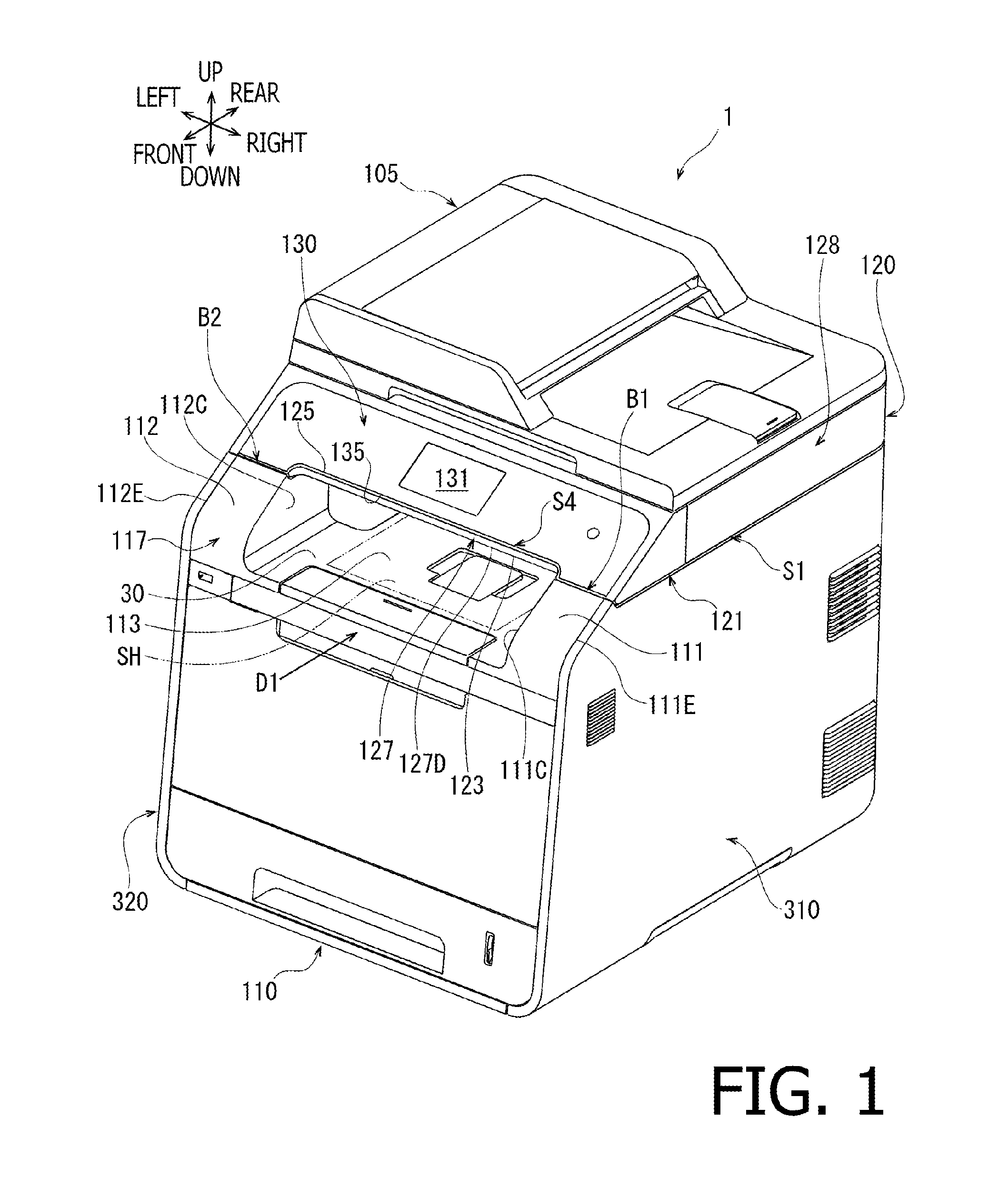
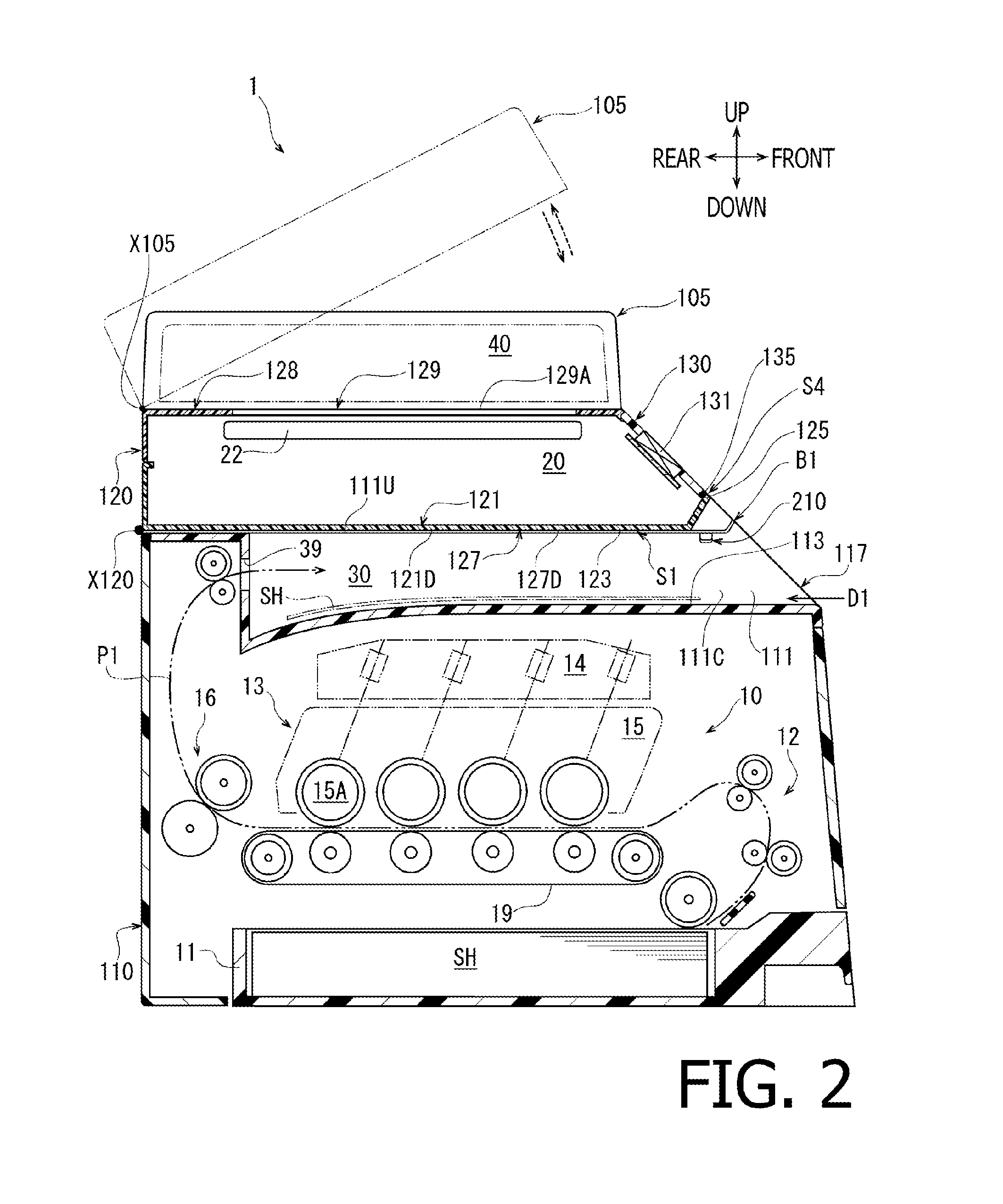
[0027]Hereinafter, a configuration of an image forming apparatus 1 according to an embodiment of the present invention will be described with reference to the accompanying drawings.

[0028]The image forming apparatus 1 is a multifunction peripheral device capable of processing a plurality of types of operations, which include, for example, an image forming operation and an image reading operation. In the following description, directions concerning the image forming apparatus 1 and parts included in the image forming apparatus 1 will be based on a user's ordinary usable posture to use the image forming apparatus 1 and referred to in accordance with orientation indicated by arrows in each drawing. Therefore, for example, a side, on which an operation panel 130 (see FIG. 1) is disposed, is defined as front, and a left-hand side for the user facing the front side of the image forming apparatus 1 is defined as left. A right-to-left or left-to-right direction of the image forming apparatus...


PUM


Abstract

An image forming apparatus, including a main body, a cover, and an upper unit, is provided. The cover includes a stackable surface to stack an ejected sheet and an attachment section extending upward from the stackable surface. The upper unit includes a base surface and an attachable section. The base surface spreads over the stackable surface with a predetermined amount of a gap reserved there-between. The attachable section is arranged in a position to adjoin the base surface to face a top surface of the attachment section and is attached to the attachment section. The attachment section has a downward dent on the top surface thereof. The downward dent adjoins a boundary part, which is a part of a gap formed in a position between the top surface and a bottom surface of the attachable section. The downward dent is a groove elongated in parallel with the boundary part.

Description

CROSS REFERENCE TO RELATED APPLICATION[0001]This application claims priority from Japanese Patent Application No. 2013-245530 filed on Nov. 28, 2013, the entire subject matter of which is incorporated herein by reference.BACKGROUND[0002]1. Technical Field[0003]An aspect of the present invention relates to an image forming apparatus.[0004]2. Related Art[0005]A conventionally known image forming apparatus may include an image forming unit, a main body, a cover of the main body, and an upper unit. The image forming unit may form an image on a sheet, the main body may accommodate the image forming unit, the cover may be placed over an upper part of the main body, and the upper unit may be disposed in an upper position with respect to the cover.[0006]The cover may include a stackable surface and attachment sections on an upper side thereof. After an image is formed on a sheet in the image forming unit, the sheet may be ejected out of the main body through an ejection opening, which is fo...

Claims


Application Information

Patent Timeline
IPC IPC(8): G03G15/00
CPCG03G21/1633G03G21/1619G03G2215/0132
Inventor SAITO, TOSHIYA
Owner BROTHER KOGYO KK
Why Eureka
Eureka Blog
Learn More