Eureka AIR delivers breakthrough ideas for toughest innovation challenges, trusted by R&D personnel around the world.

Organic electroluminescent element

Inactive Publication Date: 2014-01-02
IDEMITSU KOSAN CO LTD
View PDF0 Cites 12 Cited by
  • Summary
  • Abstract
  • Description
  • Claims
  • Application Information

AI Technical Summary

Benefits of technology

The invention provides an inorganic-compound-containing layer that is substantially made of a calcium halide and may contain other substances as long as they do not affect the operation and effects of the invention. The layer can be formed by resistance heating deposition and electron beam vapor deposition to prevent damage to an organic compound layer adjacent to the layer. The layer has a thickness of 1 nm to 50 nm and is thermally reduced by a metal layer to form metallic calcium. The metal layer can be made of aluminum, magnesium, or calcium. The invention provides a way to protect the organic compound layer and improve the performance of the inorganic-compound-containing layer in various electronic devices.

Problems solved by technology

However, since film formation by sputtering is typically required for forming a transparent conductive film, it is pointed out that an organic film is damaged due to influences by secondary electrons generated during the film formation process.
Further, only an insertion of a metal layer or a conductive oxide layer into the intermediate unit as proposed in Patent Literatures 1 and 2 is insufficient for injecting holes and electrons to the emitting unit, so that drive voltage is increased and luminous efficiency is decreased.

Method used


Image

  • Organic electroluminescent element
  • Organic electroluminescent element
  • Organic electroluminescent element

Examples


first exemplary embodiment

[0030]Arrangement of Organic EL Device

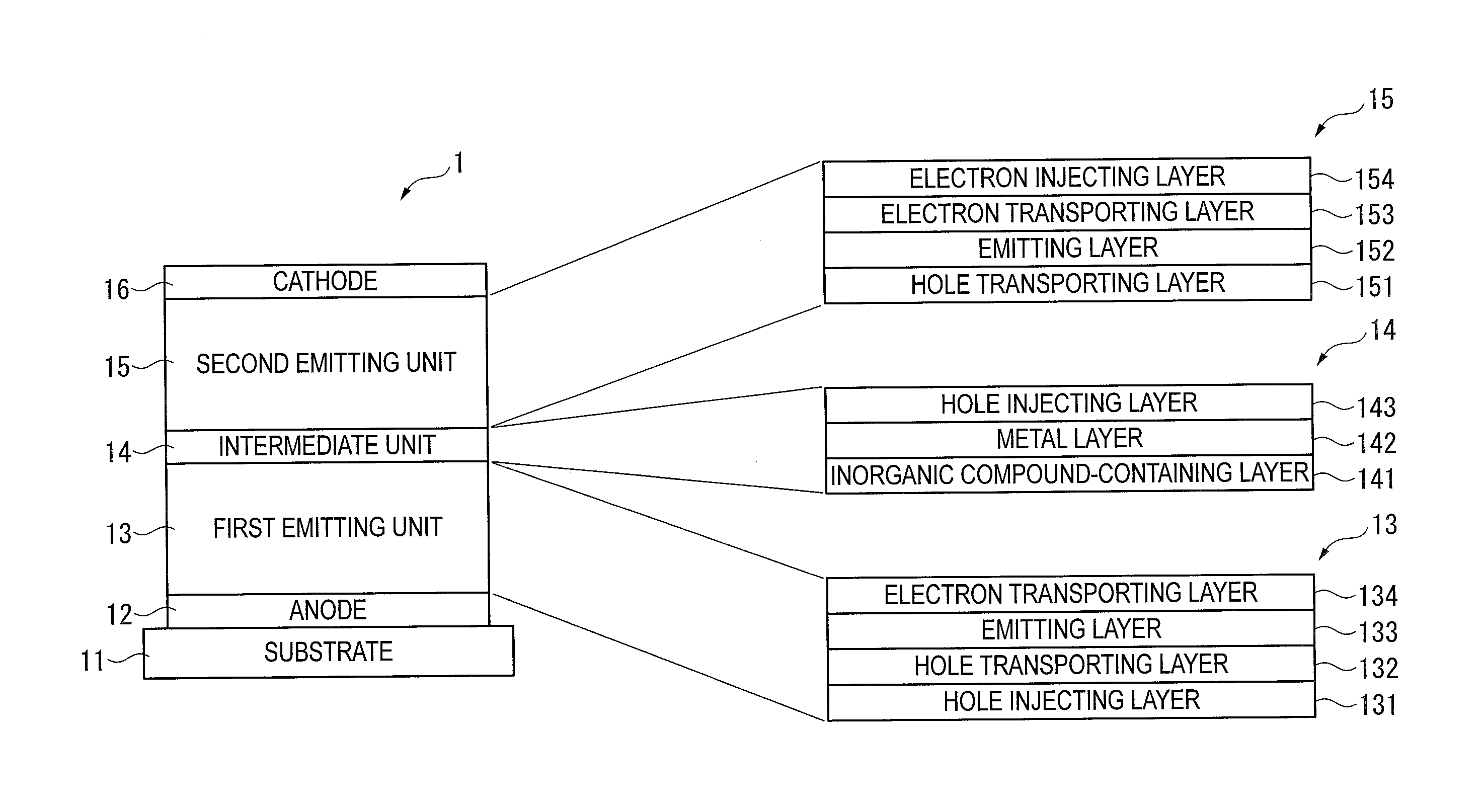
[0031]A tandem-type organic EL device includes a plurality of emitting units, e.g., a first emitting unit and a second emitting unit, as follows: anode / first emitting unit / intermediate unit / second emitting unit / cathode.

[0032]In the first exemplary embodiment, a tandem-type organic EL device 1 arranged as shown in FIG. 1 is exemplarily described. The organic EL device 1 is provided by laminating an anode 12, a first emitting unit 13, an intermediate unit 14, a second emitting unit 15 and a cathode 16 on a substrate 11 in this sequence. As shown in FIG. 1, the first emitting unit 13, the intermediate unit 14 and the second emitting unit 15 are respectively provided with a plurality of layers. The arrangements thereof are as follows.

[0033]The first emitting unit 13 includes a hole injecting layer 131, a hole transporting layer 132, an emitting layer 133, and an electron layer 134.

[0034]The intermediate unit 14 includes an inorganic-compound-contain...

second exemplary embodiment

[0192]Next, a second exemplary embodiment is described below.

[0193]In the description of the second exemplary embodiment, the same components as those in the first exemplary embodiment are denoted by the same reference signs and names to simplify or omit an explanation of the components. In the second exemplary embodiment, the same materials and compounds as described in the first exemplary embodiment are usable.

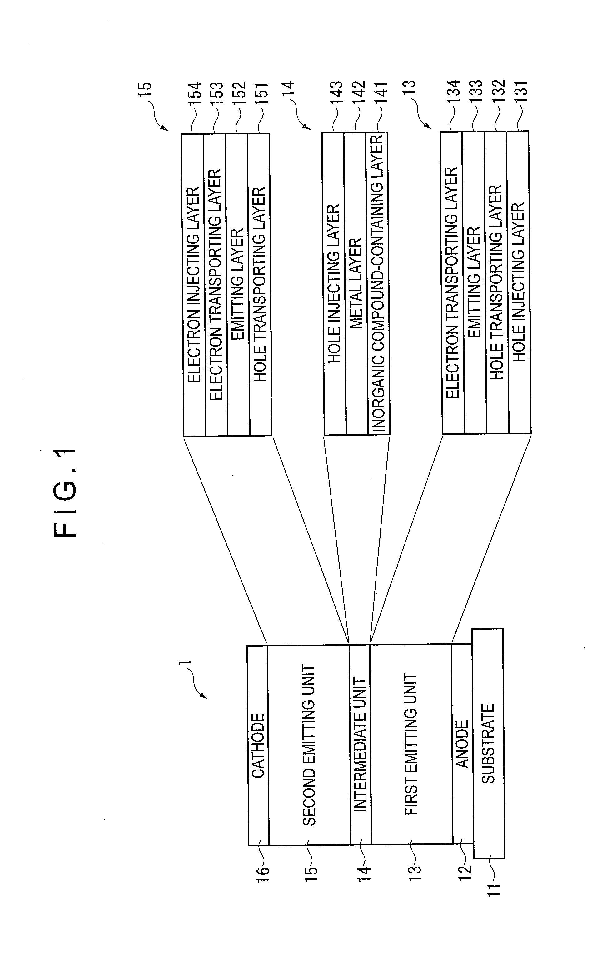
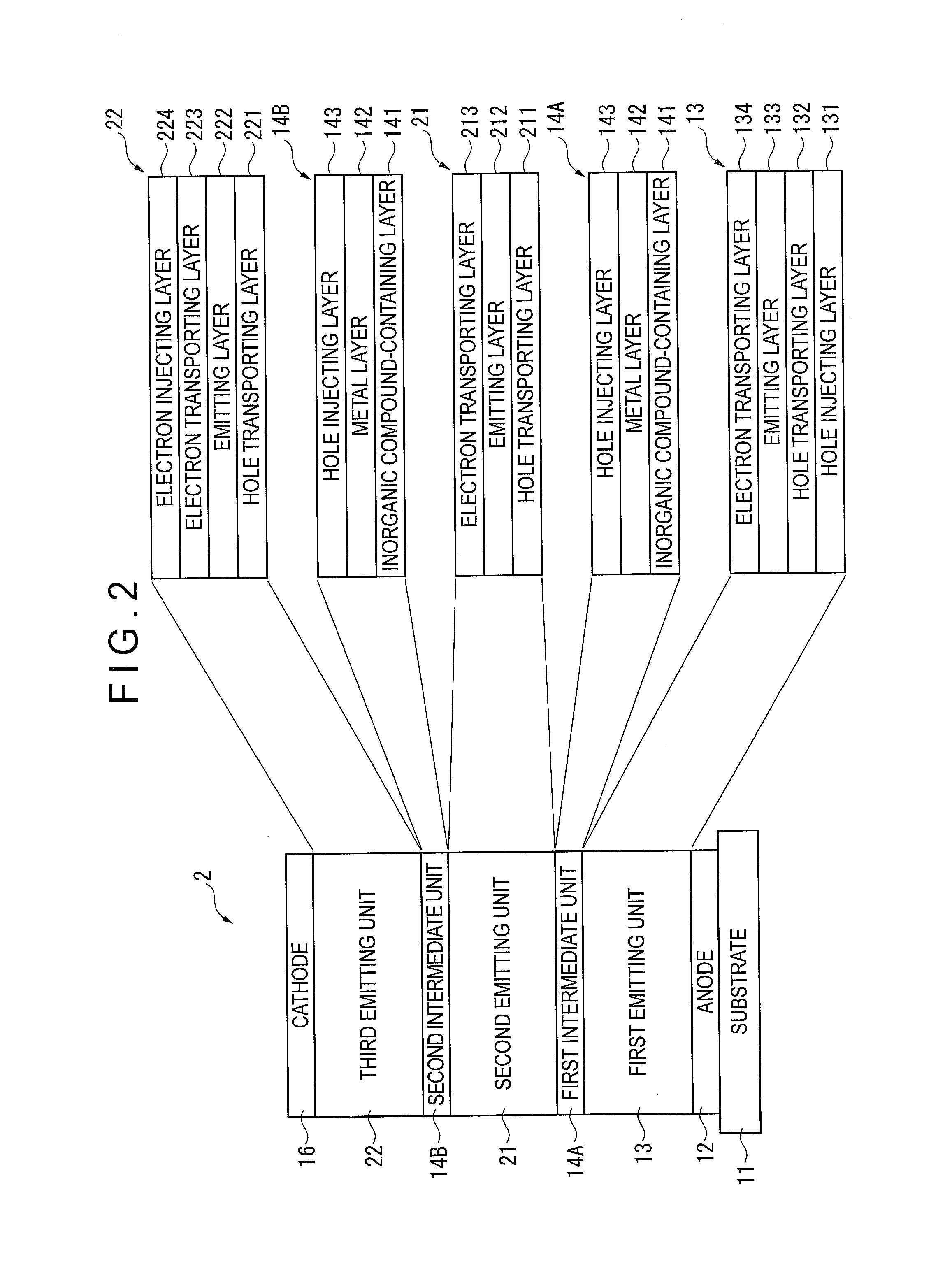
[0194]As shown in FIG. 2, an organic EL device 2 according to the second exemplary embodiment includes three emitting units and two intermediate units.

[0195]The organic EL device 2 is provided by laminating the anode 12, the first emitting unit 13, a first intermediate unit 14A, the second emitting unit 21, a second intermediate unit 14B, a third emitting unit 22 and the cathode 16 on the substrate 11 in this sequence.

[0196]In the second exemplary embodiment, the first intermediate unit 14A and the second intermediate unit 14B each include the inorganic-compound-containing l...

third exemplary embodiment

[0203]Next, a third exemplary embodiment is described below.

[0204]In the description of the third exemplary embodiment, the same components as those in the first exemplary embodiments are denoted by the same names and the like to simplify or omit an explanation of the components. In the third exemplary embodiment, the same materials and compounds as described in the first exemplary embodiment are usable.

[0205]An organic EL device 3 according to the third exemplary embodiment is arranged to be capable of emitting light by three primary colors (RGB): red (R), green (G) and blue (B). As shown in FIG. 3, a red emitting device 3R (red pixel), a green emitting device 3G (green pixel) and a blue emitting device 3B (blue pixel) are formed on a common substrate 31.

[0206]The organic EL device 3 is provided by laminating an anode 32, first emitting unit 33, intermediate unit 34, second emitting unit 35 and cathode 36 on a substrate 31 in this sequence. The first emitting unit 33 and the second...


PUM


Abstract

A tandem-type organic electroluminescence device includes an anode, a cathode opposed to the anode, and at least a first emitting unit and a second emitting unit. An intermediate unit is provided between the first emitting unit and the second emitting unit. The intermediate unit includes an inorganic-compound-containing layer and a metal layer which are laminated in this sequence from the anode. The inorganic-compound-containing layer includes calcium halide.

Description

TECHNICAL FIELD[0001]The present invention relates to an organic electroluminescence device.BACKGROUND ART[0002]There has been known an organic electroluminescence device (hereinafter, referred to as an “organic EL device”) that includes an emitting unit (in which an emitting layer is included) between an anode and a cathode and emits light using exciton energy generated by a recombination of holes and electrons that have been injected into the emitting layer.[0003]Recently, an arrangement of the organic EL device having a plurality of emitting units laminated via an intermediate unit and connected in series has been studied for improving luminous efficiency and lifetime of the organic EL device. Such a device arrangement is called a tandem-type.[0004]The tandem-type organic EL device requires holes or electrons to be injected from the intermediate unit to the adjacent emitting units. Accordingly, the intermediate unit is required to have a function for generating the holes and the ...

Claims


Application Information

Patent Timeline
IPC IPC(8): H01L51/50
CPCH01L51/5088C09K11/06H05B33/14H05B33/22C09K2211/1029C09K2211/1037C09K2211/1044C09K2211/1059C09K2211/1092C09K2211/185H10K85/622H10K85/636H10K85/615H10K85/6572H10K50/19H10K2102/103H10K50/17
Inventor ENDO, JUN
Owner IDEMITSU KOSAN CO LTD
Why Eureka
Eureka Blog
Learn More