Eureka AIR delivers breakthrough ideas for toughest innovation challenges, trusted by R&D personnel around the world.

Frictional engagement structure using multiple disks

Inactive Publication Date: 2005-12-15
JATCO LTD
View PDF4 Cites 5 Cited by
  • Summary
  • Abstract
  • Description
  • Claims
  • Application Information

AI Technical Summary

Benefits of technology

[0004] It is, therefore, an object of the present invention to provide a frictional engagement structure using multiple disks, which allows prevention of contact between the drum and the disk spring to restrain damage to the drum.

Problems solved by technology

Thus, during non-engagement of the clutch, the free disk spring rotates with respect to the outer-periphery-side drum due to rotational variations, and makes slide contact with the inner peripheral wall of the drum, causing wear of the drum.
Such wear can be prevented by hardening the drum through heat treatment, which causes, however, not only an increase in the number of working processes and in manufacturing cost, but also difficult achievement of sufficient strength even through execution of heat treatment, which is a case that the material is aluminum, for example.
With this alternative, however, the claws make contact with splines of the drum to transfer thereto torque in the direction of rotation, leading to possibility of causing damage to the splines.

Method used


Image

  • Frictional engagement structure using multiple disks
  • Frictional engagement structure using multiple disks
  • Frictional engagement structure using multiple disks

Examples


first embodiment

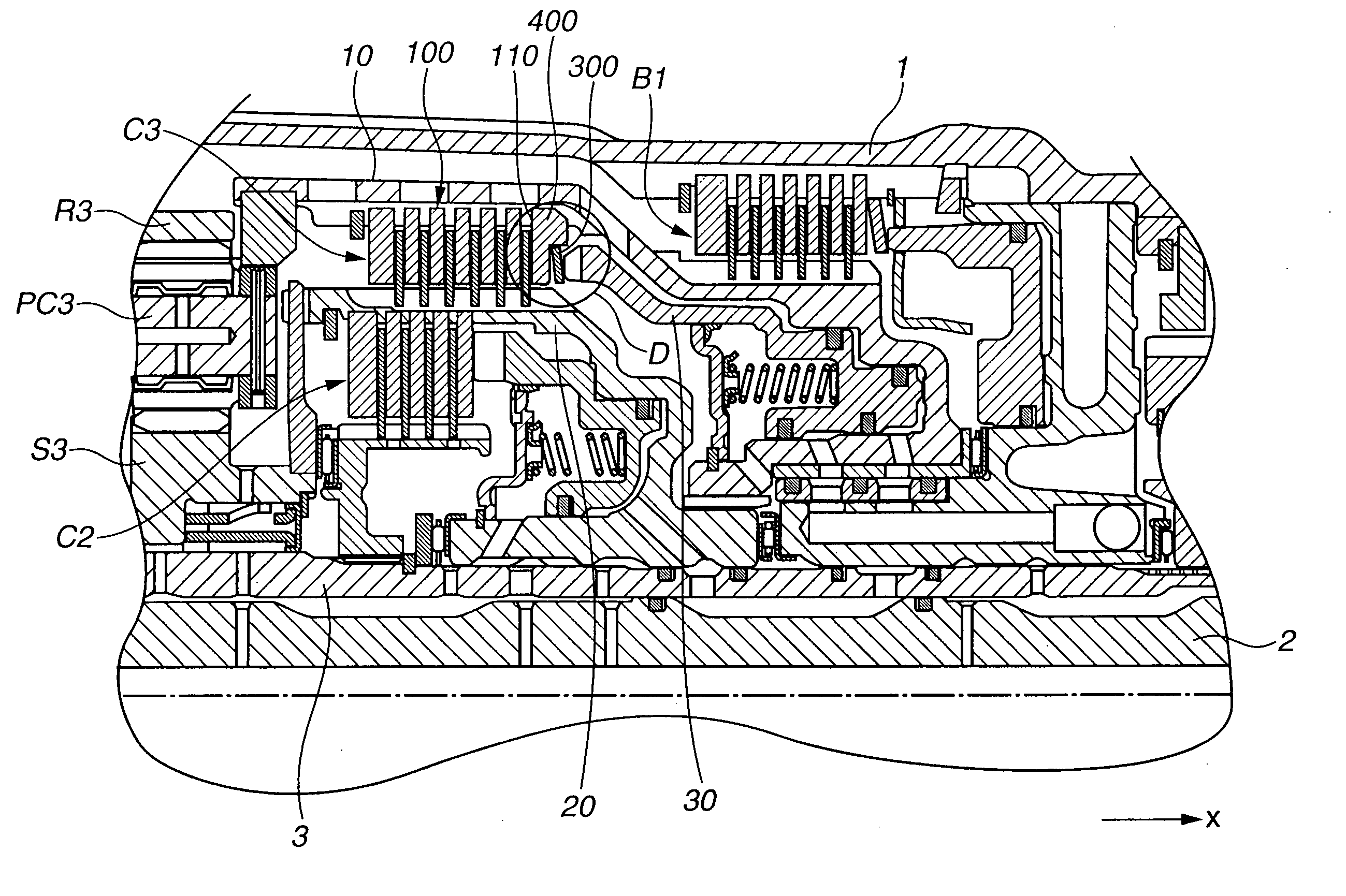
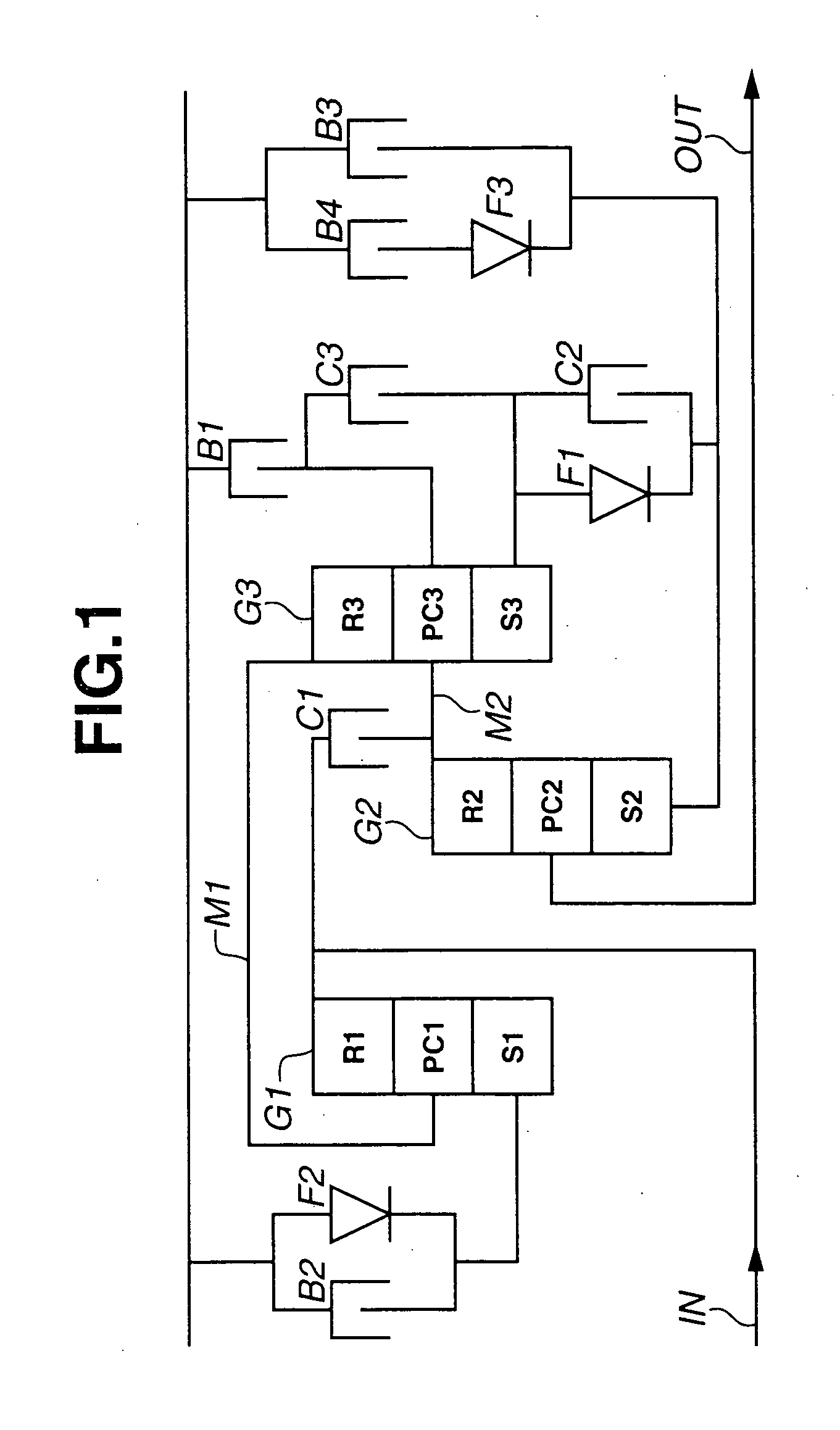
[0015] Referring to FIGS. 1-4, there is shown first embodiment of the frictional engagement structure according to the present invention. Referring to FIG. 1, the automatic transmission comprises planetary-gear sets G1, G2, G3, coupling members M1, M2, clutches C1, C2, C3, brakes B1, B2, B3, B4, one-way clutches F1, F2, F3, an input shaft IN, and an output shaft OUT.

[0016] The first, second, and third planetary-gear sets G1, G2, G3 include a single-pinion planetary-gear set. The first planetary-gear set G1 comprises a first sun gar S1, a fist ring gear R1, and a first carrier PC1 for supporting a pinion meshed with the gears S1, R1. The second planetary-gear set G2 comprises a second sun gear S2, a second ring gear R2, and a second carrier PC2 for supporting a pinion meshed with the gears S2, R2. The third planetary-gear set G3 comprises a third sun gear S3, a third ring gear R3, and a third carrier PC3 for supporting a pinion meshed with the gears S3, R3.

[0017] The first and secon...

second embodiment

[0047] Moreover, the disk spring 500 in the second embodiment includes an angle disk spring having a protrusion (bend) 530 curved over the whole circumstance in the x-axis negative direction at a position exterior of substantially the center between an inner peripheral end and an outer peripheral end. The disk spring 500 comprises an inner-periphery-side first spring portion 510 and an outer-periphery-side second spring portion 520 which extend from the protrusion 530 and have an inclination in the x-axis positive direction.

[0048] Therefore, when not pressed by the third piston 30, the disk spring 500 makes contact with the axial bearing portion 610 at the protrusion 530 only, and does not make contact with the curved portion 630 at a corner 521 which is an outer peripheral end and an x-axis negative direction end of the disk spring 500.

[0049] Next, operation of the disk spring 500 when pressed by the third piston 30 in the second embodiment will be described. When pressed by the t...


PUM


Abstract

A frictional engagement structure includes a first drum arranged at the inner periphery of a transmission casing, a second drum arranged at the inner periphery of the first drum, first friction plates splined to the casing or the first drum, second friction plates splined to the second drum, the first and second friction plates being arranged alternately in the direction of an axis of rotation of the drums, a piston for pressing the first friction plates through a disk spring and ensuring coupling between the first friction plates and the second friction plates to frictionally engage the casing or the first drum with the second drum, and a spring bearing member arranged between the first friction plates and the disk spring and including a plate portion substantially parallel to the first friction plates and the outer peripheral portion arranged substantially perpendicular to the first friction plates and interposed between the disk spring and the first drum or the casing.

Description

BACKGROUND OF THE INVENTION [0001] The present invention relates to a multiple disk clutch in a frictional engagement structure using multiple disks, and more particularly, to a cushioning disk spring and spring bearing member arranged between a clutch plate and a piston. [0002] With a multiple disk clutch in the related-art frictional engagement structure using multiple disks, driven plates and drive plates are splined to respective drums that produce relative rotation. When pressed by a piston, the driven plates and drive plates are frictionally engaged with each other to cause unitary rotation of the two drums. With such frictional engagement structure, a cushioning disk spring is arranged between the piston and the drive plates so as to prevent abrupt change in engagement force of the driven plates and drive plates, achieving smooth engagement of the clutch. In this connection, refer to Japanese document P2002-213581A. [0003] With the above multiple disk clutch, however, the dis...

Claims


Application Information

Patent Timeline
IPC IPC(8): F16D13/58F16D25/0638F16D25/12F16H3/66F16H63/30
CPCF16D13/583F16D25/0638F16D25/12F16H3/66F16H63/3026F16H2200/0047F16H2200/201
Inventor SUZUKI, YASUYUKIMURAMOTO, ATSUMIHATA, KAZUO
Owner JATCO LTD
Why Eureka
Eureka Blog
Learn More