
Method for controlling ophthalmic device

Active Publication Date: 2015-06-04
MEDIZS
View PDF2 Cites 7 Cited by
  • Summary
  • Abstract
  • Description
  • Claims
  • Application Information

AI Technical Summary

Benefits of technology

The present invention provides a method for wireless control of ophthalmic instruments using a conventional smart pad. This allows for easy operation and control of the instruments, such as an auto phoropter or auto chart instrument. The smart pad can display an image of the instrument and use finger touch or movement to control it. The invention also allows for integrated management and post management of examination results from the ophthalmic instruments, saving previous data and using it in controlling the instruments. Overall, the invention simplifies the process of controlling and managing ophthalmic instruments, providing better accessibility to eye care professionals.

Problems solved by technology

But the whole cost for the digital refractor is high because the operation panel is necessary for the control of the digital refractor.
Furthermore it is difficult to use an auto chart instrument of the other maker due to the compatibleness problem between the operation panel.
In addition, since the measurement data measured by the respective ophthalmic instruments cannot be transferred therebetween, the measurement data may be given by the display or the printed paper and cannot be saved, which makes integrated management and post management for the measurement data difficult.

Method used


Image

  • Method for controlling ophthalmic device
  • Method for controlling ophthalmic device
  • Method for controlling ophthalmic device

Examples


Embodiment Construction

[0036]Reference will now be made in detail to the preferred embodiments of the present invention, examples of which are illustrated in the accompanying drawings.

[0037]Hereinafter, method for wireless control of ophthalmic instrument in accordance with the present invention will be explained in more detail with reference to the attached drawings.

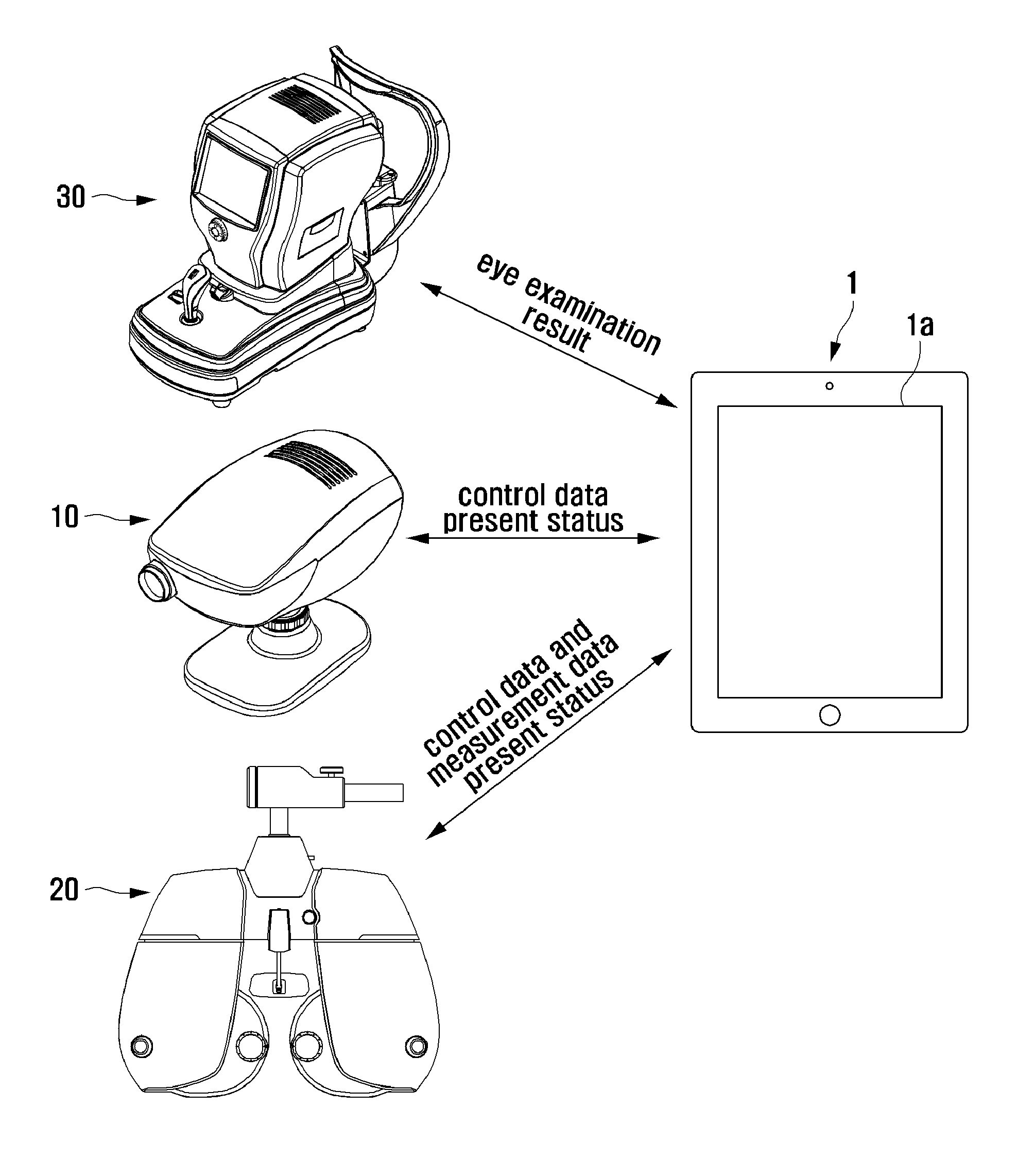
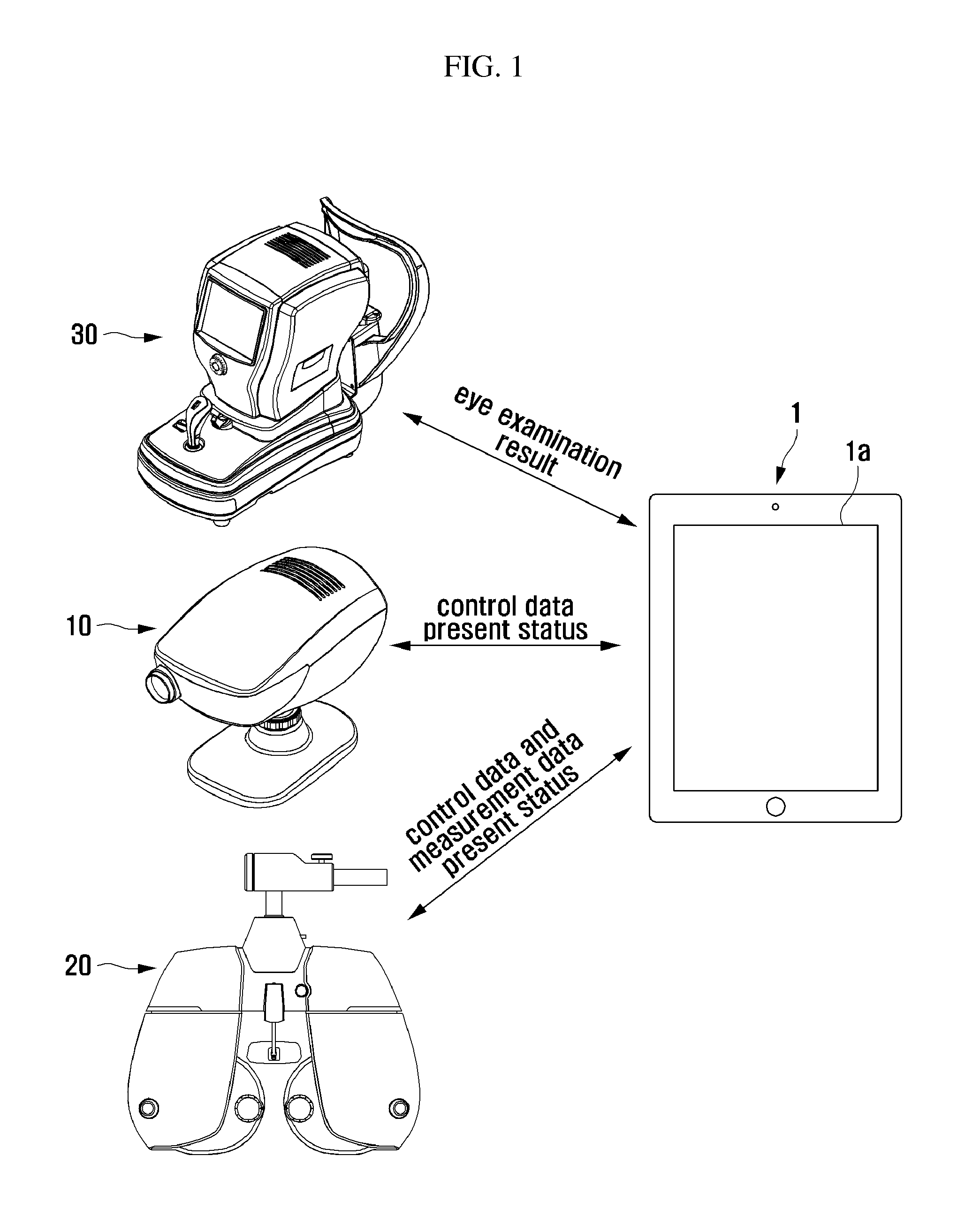
[0038]An ophthalmic instrument system to which the method for wireless control of ophthalmic instrument in accordance with the present invention is applied, may include at least one auto chart instrument 10, at least one auto phoropter 20, and a smart pad 1 for wireless control of at least one auto chart instrument 10 and at least one auto phoropter 20 as shown in FIG. 1.

[0039]The auto chart instrument 10 is an ophthalmic instrument for measuring eyesight by displaying chart images including letters, figures, etc., and may be a chart projector, an LCD chart, etc. which displaying chart images including letters, figures, etc. for measuring eye...


PUM


Abstract

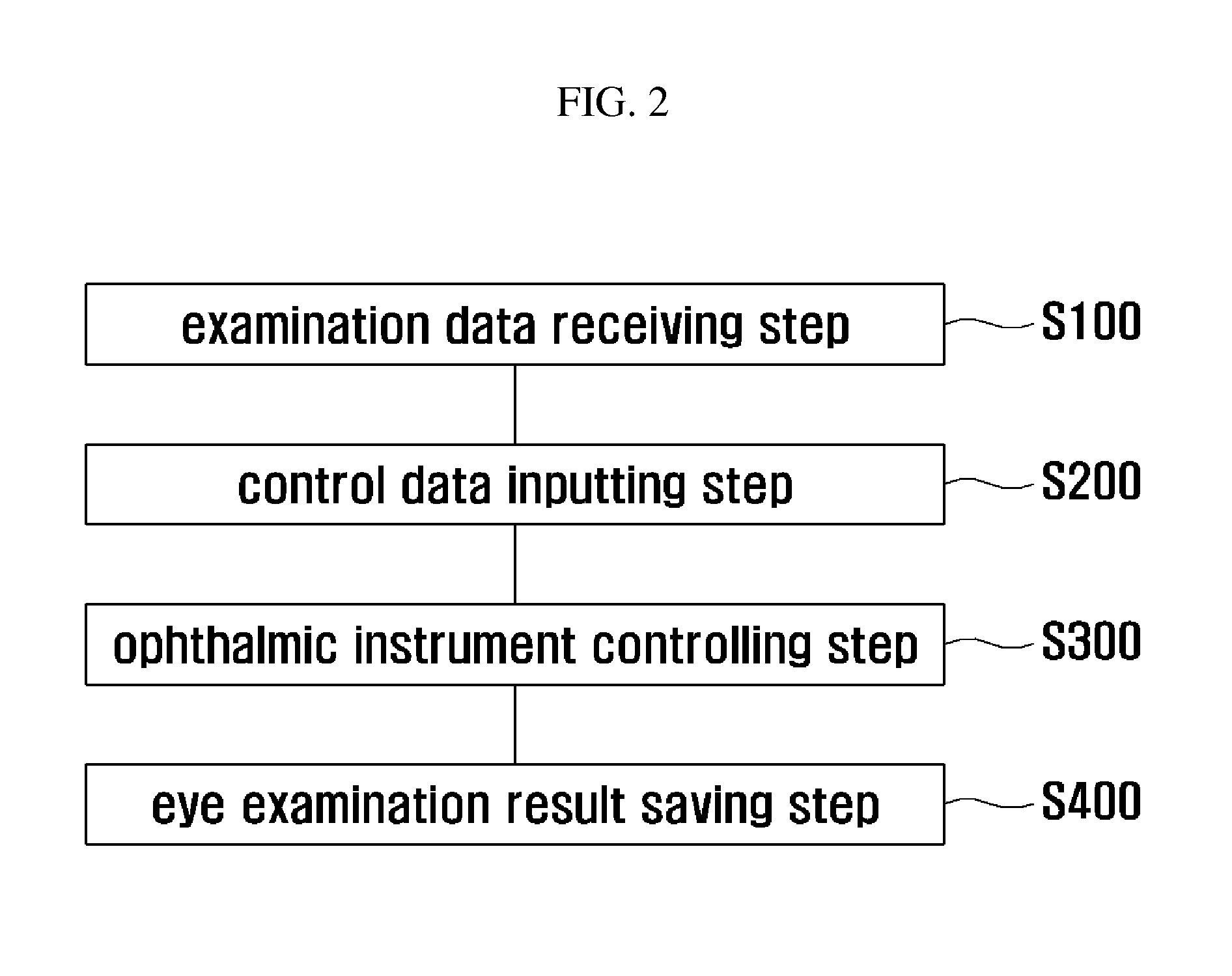
A method for wireless control of an auto chart instrument and an auto phoropter by using a smart pad, comprising: control data inputting step for being inputted with control data for wireless control of one of the auto chart instrument and the auto phoropter; and controlling step for controlling one of the auto chart instrument and the auto phoropter according to the control data inputted during the control data inputting step, is disclosed.

Description

FIELD OF THE INVENTION[0001]The present invention related to an ophthalmic instrument system, and more particularly to method for controlling ophthalmic instrument for eye examination.DESCRIPTION OF THE RELATED ART[0002]A phoropter (US trademark of Reichert Technologies)) is an instrument commonly used by eye care professionals during an eye examination, containing different lenses used for refraction of the eye during sight testing, to measure an individual's refractive error and determine his or her eyeglass prescription.[0003]The phoropter includes a plurality of lenses such as spherical lenses, cylinder lenses, etc. which are combined for eye examination.[0004]In addition, the phoropter performs eye tests such as eyesight test and color blindness test together with another ophthalmic instrument, a chart projector.[0005]As a phoropter there are two types, a manual phoropter manually operated by rotating dials, and auto phoropter (digital refractor) automatically controlled by an ...

Claims


Application Information

Patent Timeline
IPC IPC(8): A61B3/028A61B3/00
CPCA61B3/0033A61B3/0285A61B3/032A61B3/18A61B3/028A61B3/12
Inventor PARK, JI HYOUNGKIM, YU KYEOMLEE, KI DONGJIN, SUNG YUNKIM, BO RA
Owner MEDIZS
Learn More