
Infusion pump

a technology of infusion pump and pump body, which is applied in the direction of infusion device, suction device, intravenous device, etc., to achieve the effect of preventing a bubble sensor

Active Publication Date: 2015-06-04
TERUMO KK
View PDF3 Cites 41 Cited by
  • Summary
  • Abstract
  • Description
  • Claims
  • Application Information

AI Technical Summary

Benefits of technology

The present invention relates to an infusion pump that prevents bubble sensors from detecting bubbles accurately. The invention achieves this by reducing bubble sensor errors caused by bubbles remaining inside infusion tubes. Infusion pumps often have a narrowed flow path where bubbles can form and be detected by a bubble sensor. However, this can lead to errors as bubbles can also form at a liquid stagnant portion where the flow rate changes quickly. The invention prevents this by reducing the stagnant portion of the medicinal solution and avoiding a part of the medicinal solution remaining inside the narrowed flow path. This results in an improved accuracy of bubble detection. The invention also integrates a projecting portion that reduces the number of components compared to separate components.

Problems solved by technology

Due to this, the bubble sensor may determine that the medicinal solution exists inside the infusion tube and erroneously detects that there is no bubble although the bubble actually exists inside the infusion tube.

Method used


Image

  • Infusion pump
  • Infusion pump
  • Infusion pump

Examples


Embodiment Construction

[0034]In the following, a preferred embodiment of the present invention will be described in detail with reference to accompanying drawings.

[0035]Note that the embodiment described below contains various technical preferred limitations for being a preferable example of the present invention, but a technical scope of the present invention is not limited thereto unless otherwise particularly specified to limit the present invention in the following description.

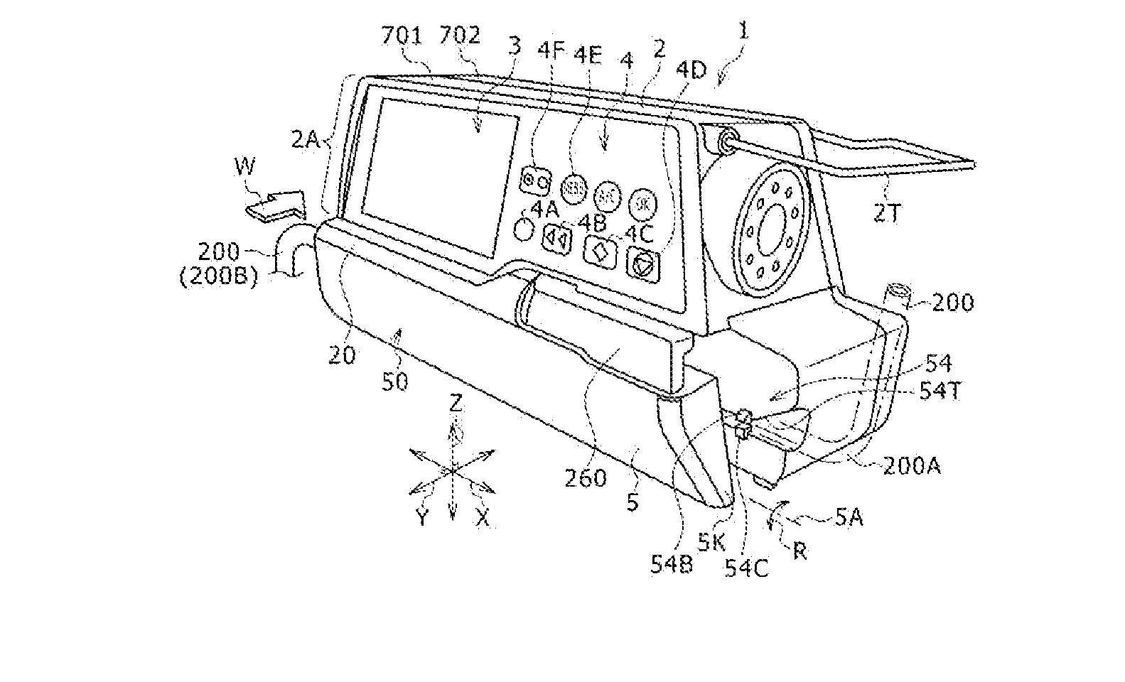
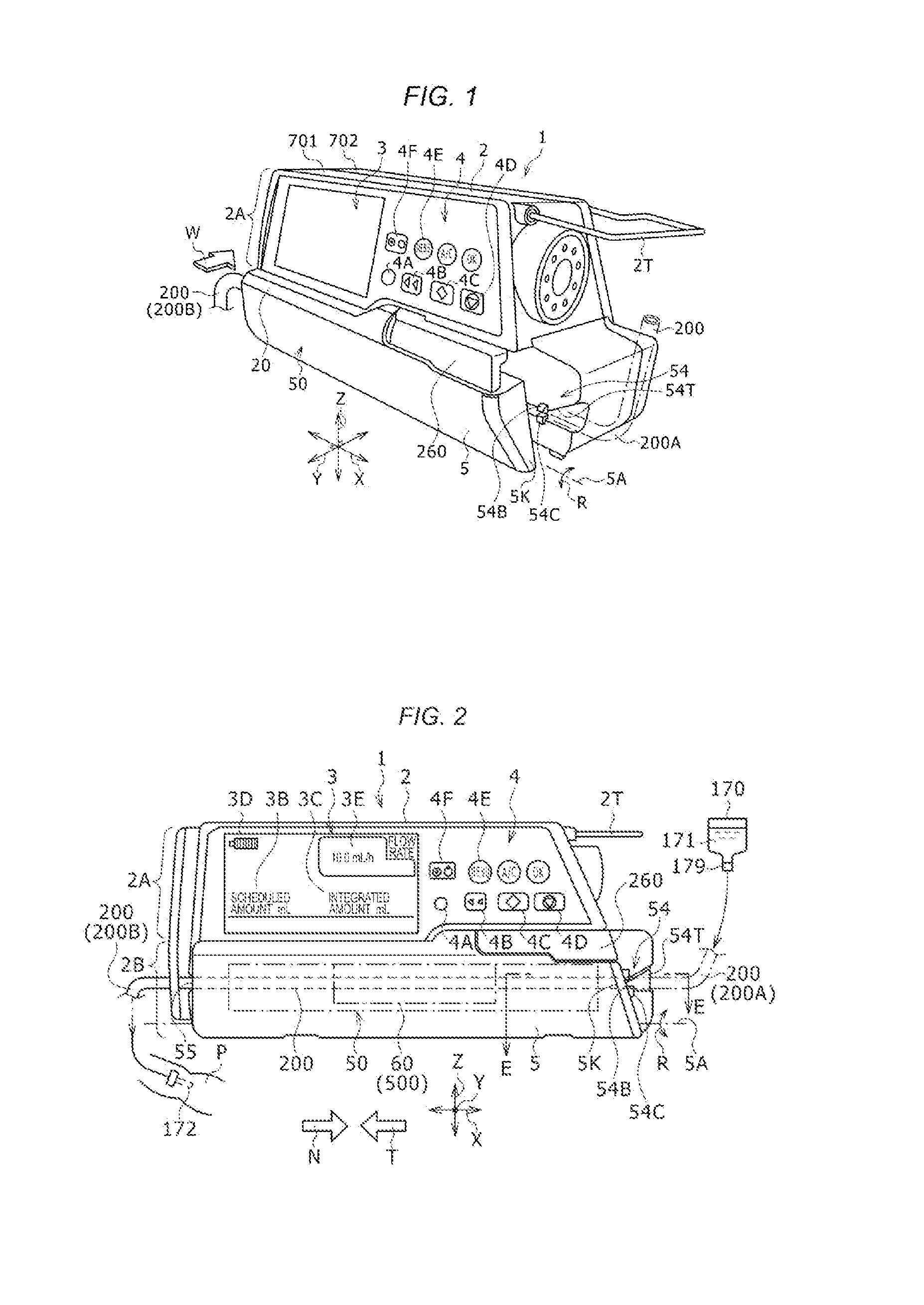
[0036]FIG. 1 is a perspective view illustrating a preferred embodiment of an infusion pump according to the present invention. FIG. 2 is a perspective view illustrating the infusion pump illustrated in FIG. 1, viewed from W-direction.

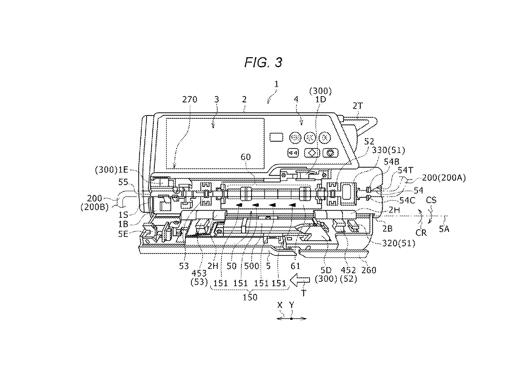
[0037]An infusion pump 1 illustrated in FIGS. 1 and 2 is used, for example, in an intensive care unit (ICU, CCU, NICU) and the like, and is a continuous micro-injection pump used for injecting a micro amount of a medicinal solution, such as anticancer drugs, anesthetics, a chemotherapeutic agents, b...


PUM


Abstract

An infusion pump includes a main body; a tube attachment section, in which an infusion tube is attachable; a liquid feed driving unit disposed inside the main body; an access cover mounted on the main body and configured to cover the infusion tube when the infusion tube is attached to the tube attachment section when closed; and a bubble detection unit. The bubble detection unit includes a first member disposed at the access cover and a second member disposed at the main body. The infusion pump is configured such that, when the infusion tube is attached to the tube attachment section, a first space of the infusion tube is located between the first member and the second member of the bubble detection unit a second space of the infusion tube is located downstream of the first space, and the second space is smaller than the first space.

Description

CROSS-REFERENCE TO RELATED APPLICATIONS[0001]This application is a continuation application filed under 35 U.S.C. 111(a) claiming the benefit under 35 U.S.C. §§120 and 365(c) of PCT International Application No. PCT / JP2012 / 005124 filed on Aug. 10, 2012, the entire content of which is hereby incorporated by reference in its entirety.BACKGROUND[0002]1. Technical Field[0003]The present disclosure relates to an infusion pump for feeding medicinal solution and the like to a patient. Particularly, the present disclosure relates to the infusion pump in which an infusion tube is attached to the infusion pump in a horizontal direction to feed liquid.[0004]2. Background Art[0005]An infusion pump is used in, for example, an intensive care unit (ICU) or the like, and applied to feed medicinal solution to a patient for a relatively long period with high accuracy. A predetermined medicinal solution bag (infusion bag) is disposed above the infusion pump. An infusion tube hung from the medicinal so...

Claims


Application Information

Patent Timeline
Patent Type & Authority Applications(United States)
IPC IPC(8): A61M5/36A61M5/162A61M5/142
CPCA61M5/365A61M5/162A61M5/142
Inventor NAKANISHI, MASARU
Owner TERUMO KK
Learn More