Aircraft Fuselage

Active Publication Date: 2015-06-04
AIRBUS OPERATIONS GMBH +1
View PDF7 Cites 2 Cited by
  • Summary
  • Abstract
  • Description
  • Claims
  • Application Information

AI Technical Summary

Benefits of technology

The patent text describes an energy absorption system for aircraft fuselages that can protect against unforeseeable damage during crashes. The system includes energy absorption devices that are connected to the backing structure of the fuselage through rope pulleys, cable pulleys, wire pulleys, belt pulleys, or chain pulleys. These devices are placed in cargo hold regions that remain intact during a crash. The system also includes support portions on the floor support that act as levers to absorb impact energy. Additionally, the system includes rivets or bolts that are designed to pull through in the event of a crash, reducing the impact energy. The use of vertical supports can also help relieve strain on lateral structural portions in the region of the cabin floor framework. Overall, the system provides a controlled and effective means to absorb impact energy and protect the aircraft fuselage during a crash.

Problems solved by technology

Thus in the region of the quasi-joints initial failure of the backing structure occurs.
At impact, in the region of the quasi joints failure of the backing structure occurs, for example in the form of a frame element fracture or failure, and thus flattening of the outer skin in the region of the cargo hold occurs.

Method used


Image

  • Aircraft Fuselage
  • Aircraft Fuselage
  • Aircraft Fuselage

Examples


Embodiment Construction

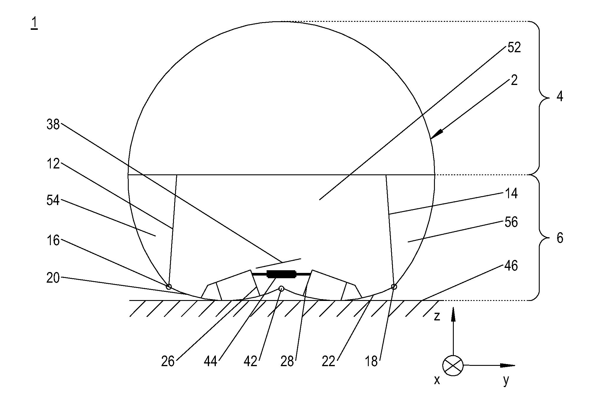
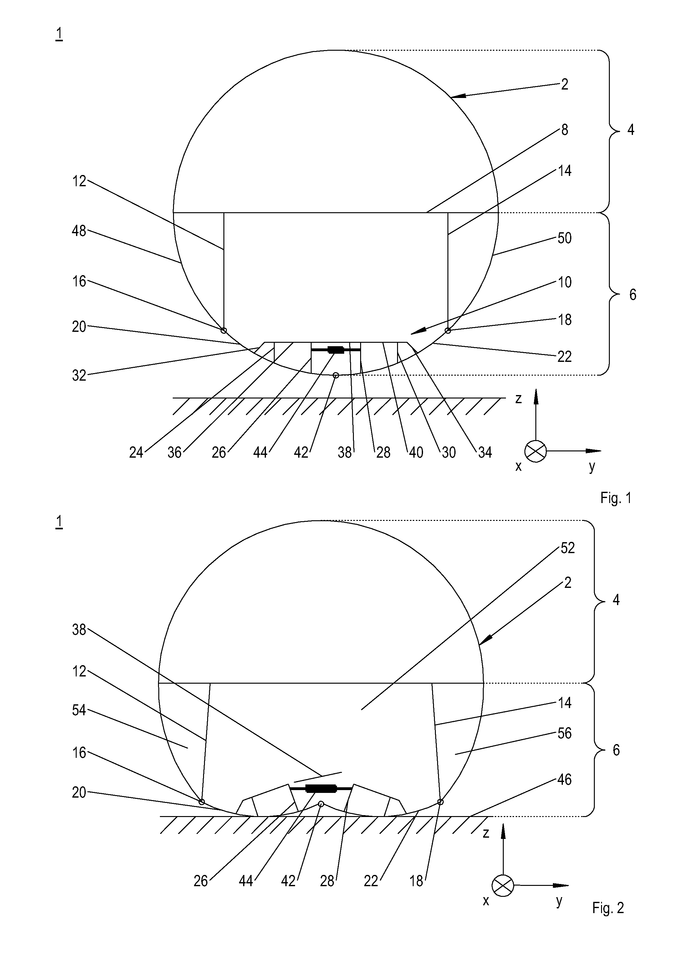
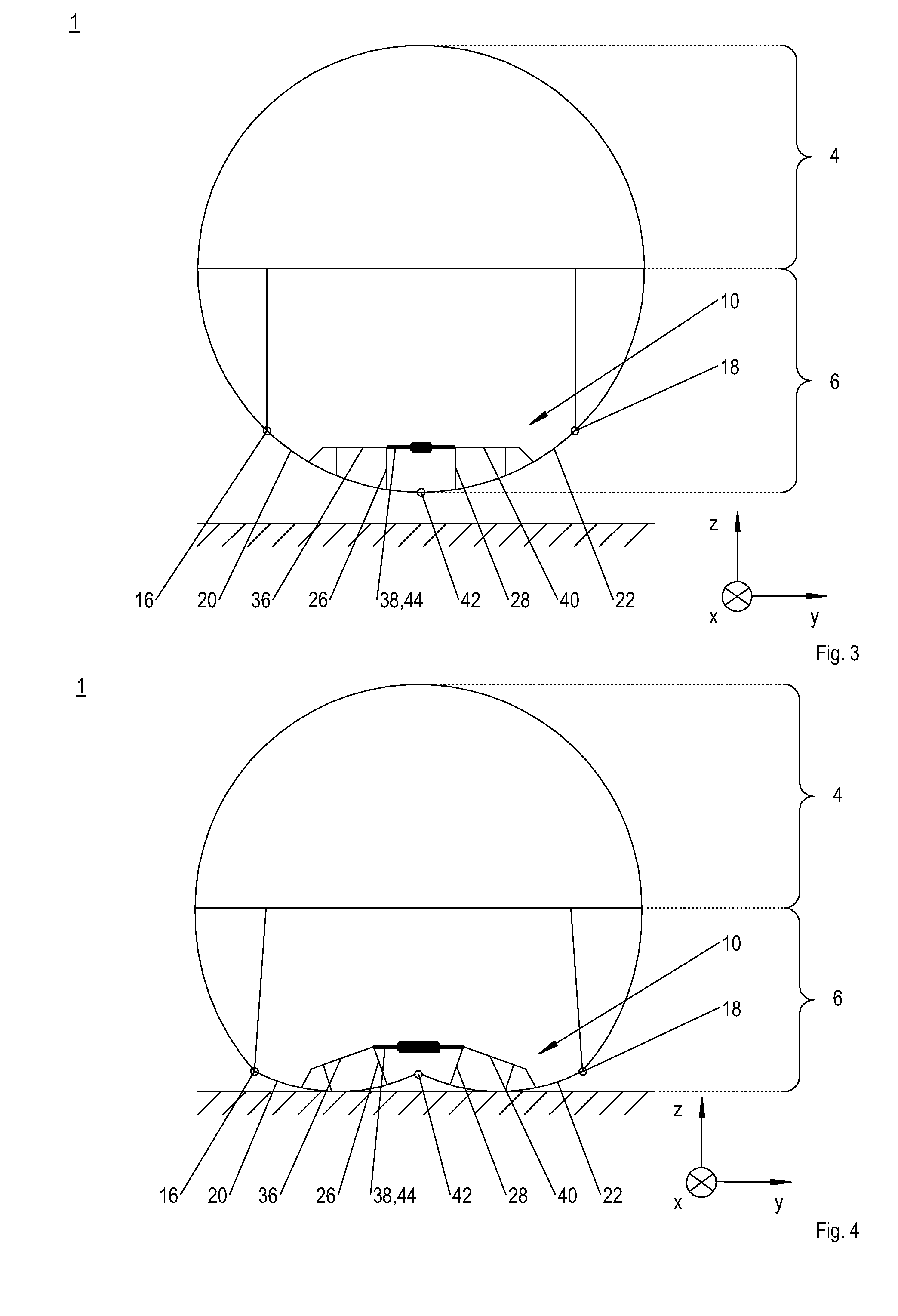
[0034]In the following FIGS. 1 to 14, quasi-joints 16, 18, 42, 70, 72, 74, 76 according to the invention are shown as circles. The representation as circles is merely intended to make it easier to understand the invention.

[0035]It should be pointed out expressly that the following figures show only exemplary embodiments of an aircraft fuselage 1 according to the invention. The exemplary embodiments are not to be interpreted as limiting the scope of protection of the invention. Furthermore, it should be pointed out that, basically, individual features of the exemplary embodiments can be combined. The individual combinations of features are not limited to the respective exemplary embodiment. In particular, the following should be noted:

[0036]Even though in the exemplary embodiments the aircraft fuselage 1 is always shown comprising vertical supports 12, 14 that support a cabin floor framework 8, the aircraft fuselage 1 can also be constructed without such vertical supports 12, 14. Suc...


PUM


Abstract

An aircraft fuselage including an outer skin that is stiffened by way of a backing structure and that delimits at least one passenger cabin and one cargo hold. In the vertical direction of the fuselage, the cargo hold is arranged below the passenger cabin. The backing structure in the cargo hold above a cargo-hold floor framework comprises at least two lateral quasi-joints, and below the cargo-hold floor framework comprises at least one further quasi-joint. In the cargo hold, in the longitudinal direction of the fuselage, a multitude of energy absorption devices, arranged one behind the other and acting in the transverse direction of the fuselage, are arranged for absorbing tensile loads.

Description

BACKGROUND OF THE INVENTION[0001]The invention relates to an aircraft fuselage.[0002]Generally speaking, aircraft fuselages comprise an outer skin that is stiffened by way of a backing structure and that in the vertical direction of the fuselage delimits an upper passenger cabin or an above-floor region and a lower cargo hold or below-floor region. The backing structure usually comprises stringers that extend in the longitudinal direction of the fuselage, and frame elements that extend in the circumferential direction of the fuselage. The passenger cabin and the cargo hold each comprise a floor framework, wherein the cabin floor framework is supported on the backing structure in the cargo hold.[0003]Conventionally, the outer skin and the backing structure are made from metal materials such as aluminium alloys. However, present-day fuselage concepts provide for the metal materials to be replaced by fiber-composite materials, in particular carbon-fiber-reinforced plastics (CFRPs). Bec...

Claims


Application Information

Patent Timeline
IPC IPC(8): B64C1/06
CPCB64C1/062
Inventor SIEMETZKI, MARKUSBAUTZ, BRIANMARGULL, LARSWAIMER, MATTHIASBERGMANN, TIMHEIMBS, SEBASTIANSCHATROW, PAUL
Owner AIRBUS OPERATIONS GMBH
Why Eureka
Try Eureka