This helps you quickly interpret patents by identifying the three key elements:
Problems solved by technology
Method used
Benefits of technology
Benefits of technology
[0028]The timing of the collision of the chain rollers or bushings with the sprocket is shifted, and the kinetic energy of the impact of the rollers or bushings with the sprocket teeth is reduced. Vibration at a frequency corresponding to the number of sprocket teeth multiplied by the rate of rotation of the sprocket is therefore reduced. Furthermore, since there is a large difference between the overall noise and the noise at a frequency corresponding to the number of sprocket teeth multiplied by the rate of rotation of the sprocket is large, “gating” noises are reduced.
[0029]Since the pitch angles are arranged irregularly, and the pitch angles larger than the standard pitch angle are greater than the number of pitch angles smaller than the standard pitch angle, vibration and noise can be reliably reduced without impairing the endurance of the sprocket.
[0030]Since the teeth are integrally molded with the sprocket by sintering, neither machining requiring complicated control, nor rolling, is needed. Consequently, manufacture of the sprocket is easy. Furthermore, since more lubricant can be held in the surface of a sintered sprocket than in a conventional sprocket, frictional noise, due to sliding contact of a bushing or roller of a chain with the plural sprocket teeth having a varying pitch, is reduced.
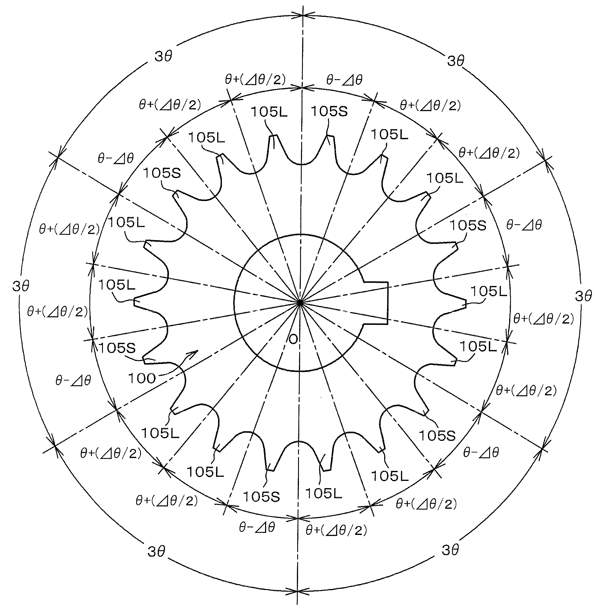
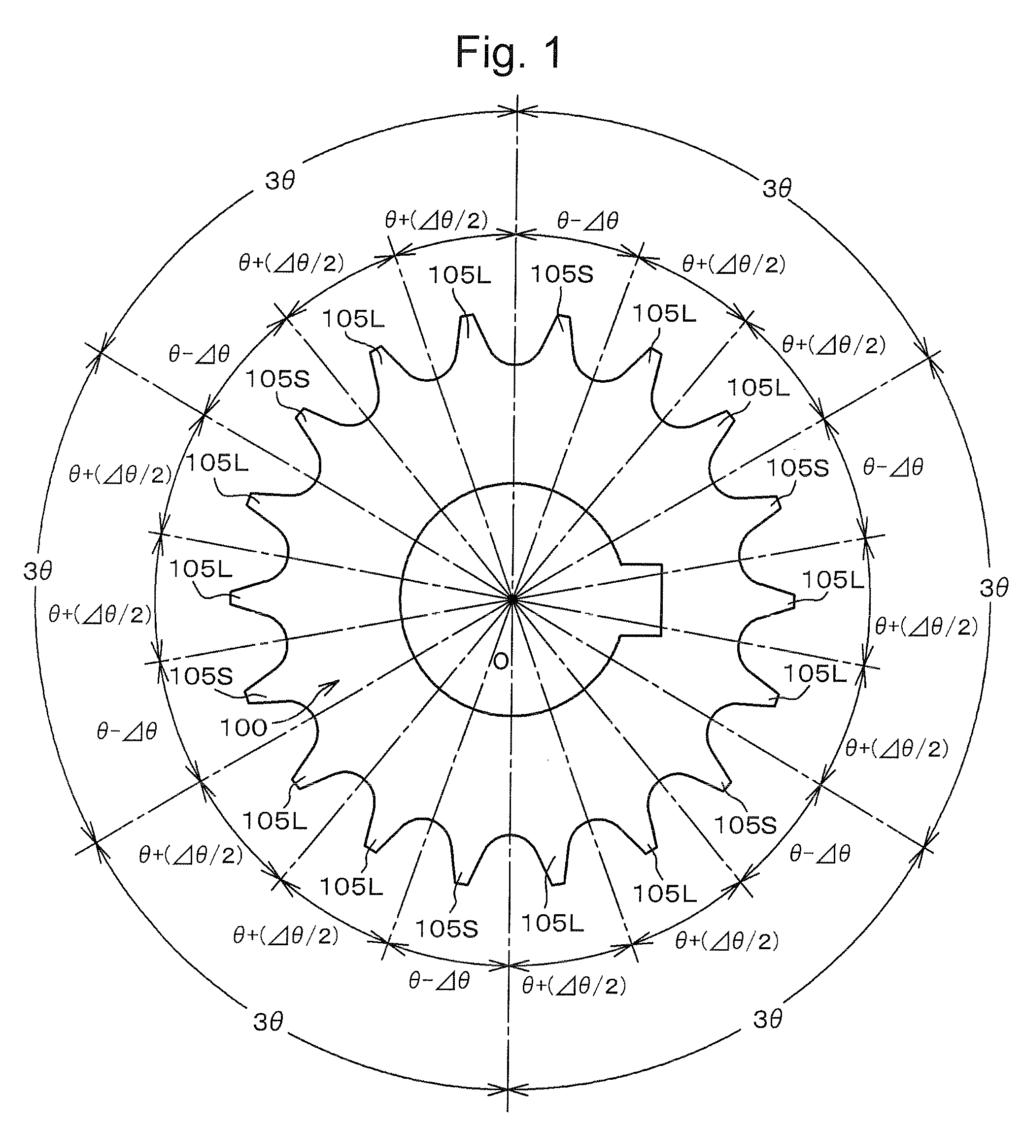
[0031]Where the value of the standard tooth form pitch angle is θ, the minimum pitch angle is θ−Δθ, and the maximum pitch angle is less than θ+Δθ, vibration and noise can be even more reliably reduced without impairment of the endurance of the sprocket.
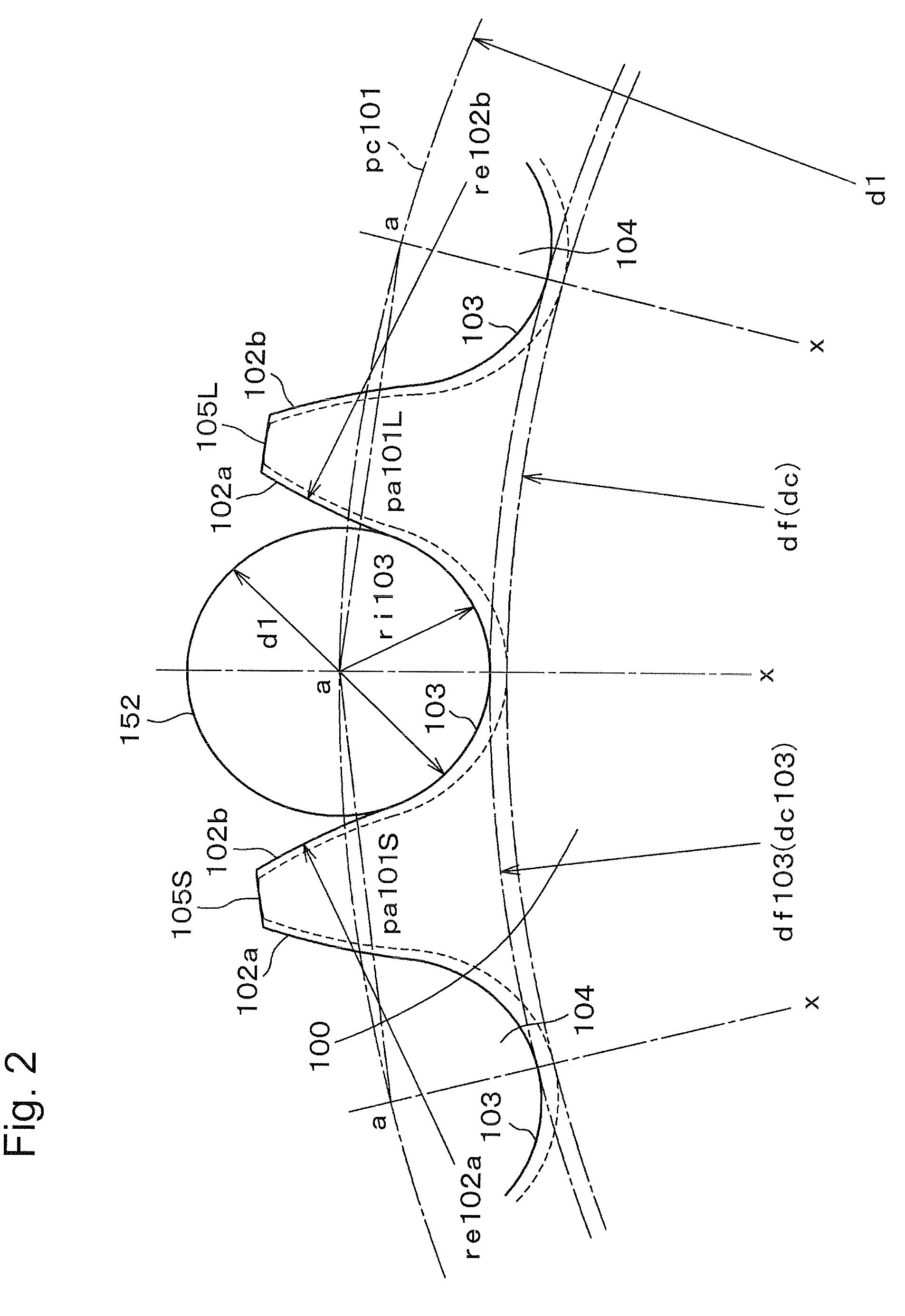
[0032]Preferably, the root diameter of the sprocket is greater than the root diameter of a standard sprocket having the same pitch circle diameter and the same number of teeth. A roller or bushing comes into engagement with a back tooth surface of a tooth in substantially tangential direction. Therefore, the impact due to movement of the roller or bushing relative to the sprocket is low, and vibration and noise due to the impact of the roller or bushing with the sprocket can be reduced. Additionally, when a preceding roller and bushing moves relatively about an immediately following roller or bushing on disengagement from the sprocket, the preceding roller or bushing separates smoothly from the sprocket, and a further reduction of vibration and noise can be realized.
Problems solved by technology
However, where the load on the timing transmission is at a high level, and chain tension is high, it has become difficult to suppress noise sufficiently.
Thus, upon engagement of the following roller 152 with the tooth gap bottom the kinetic energy of the roller is transmitted to the tooth gap bottom without buffering, generating a large amount of vibration and noise.
However since the roller becomes sandwiched between opposed tooth surfaces, smooth disengagement of the roller from the sprocket is prevented, and vibration of the chain takes place on the side at which the chain disengages from the sprocket, generating noise.
Method used
Image
Click on the blue label to locate the original text in one second.
Reading with bidirectional positioning of images and text.
Examples
first embodiment
[0056]Here as in the first embodiment, Δθ is preferably less than ¼ of the standard pitch angle θ, so that the pitch angles are all within a range in which a standard chain is able to engage with the sprocket. That is, Δθ<θ / 4.
[0057]The teeth having the standard angle θ may provided in various numbers and in various positions on the sprocket. When the number of standard sprocket teeth is evenly divisible by N the number of teeth having the standard pitch θ can be zero.
[0058]Furthermore, one set or more in a plurality of sets of teeth in the sprocket 200 may be composed of N teeth, each having a pitch angle θ. Thus, in the sprocket, one or more sets of teeth can be composed of one tooth 205S, having a pitch angle θ−Δθ and N−1 teeth 205L, each having a pitch angle θ+(Δθ / (N−1)) may exist. The remaining teeth, having a pitch angle θ may be arranged at any positions.
[0059]The tooth form of the teeth of sprocket 200 is the same as that of the teeth of the first embodiment, shown in FIG. 2....
third embodiment
[0060]In the invention, shown in FIG. 4, a sprocket 300 has two kinds of teeth having different pitch angles. One kind of tooth is tooth 305S having a pitch angle θ−Δθ, which is smaller than the standard pitch angle θ, and another kind of tooth is tooth 305L, having a pitch angle θ+(Δθ / (T−1)), which is larger than the standard pitch angle θ. The sprocket 300, comprises one tooth 305S having the pitch angle θ−Δθ, and the all remaining teeth 305L have the pitch angle θ+(Δθ / (T−1)).
[0061]The total number of teeth of the sprocket 300 is T, and the total angle is 360°. The tooth 305S, having the pitch angle θ−Δθ becomes an irregularity along the circumferential direction of the pitch circle. Each of the T−1 teeth 305L, has a pitch angle θ+(Δθ(T−1)) larger than the standard pitch angle θ. The maximum of the pitch angle θ+(Δθ / (T−1)) is less than θ+Δθ.
[0062]As in the first and second embodiments, Δθ is preferably less than ¼ of the standard pitch angle θ, so that the pitch angles are all wit...
PUM
Abstract
A sprocket for a chain drive using a roller or bushing chain has a plurality of different pitch angles, including both pitch angles larger than the standard pitch angle, and pitch angles smaller than the standard pitch angle. The number of pitch angles in the sprocket larger than the standard pitch angle is greater than the number of pitch angles in the sprocket smaller than the standard pitch angle. The sprocket teeth are integrally molded with the sprocket by sintering.
Description
CROSS-REFERENCE TO RELATED APPLICATION[0001]This application claims priority on the basis of Japanese patent application 2008-126256, filed May 13, 2008. The disclosure of Japanese application 2008-126256 is hereby incorporated by reference.FIELD OF THE INVENTION[0002]The invention relates to a sprocket for use with a transmission chain. The periphery of the sprocket has a plurality of teeth separated from one another by tooth grooves, each groove having a tooth gap bottom continuous with facing surfaces of two adjacent teeth. In a chain transmission, rollers of a roller chain, or bushings of a bushing chain, engage with the tooth gaps. It is desirable to reduce noises generated when the roller of a roller chain or the bushing of a bushing chain engages with a sprocket tooth, and to achieve smooth disengagement of the rollers or bushings from the sprocket.BACKGROUND OF THE INVENTION[0003]Chain transmissions in which a chain is in meshing engagement with a driving sprocket and one or...
Claims
Application Information
Patent Timeline
Application Date:The date an application was filed.
Publication Date:The date a patent or application was officially published.
First Publication Date:The earliest publication date of a patent with the same application number.
Issue Date:Publication date of the patent grant document.
PCT Entry Date:The Entry date of PCT National Phase.
Estimated Expiry Date:The statutory expiry date of a patent right according to the Patent Law, and it is the longest term of protection that the patent right can achieve without the termination of the patent right due to other reasons(Term extension factor has been taken into account ).
Invalid Date:Actual expiry date is based on effective date or publication date of legal transaction data of invalid patent.

