Air intake hood for turbine inlet filter house

a technology of air intake hood and turbine, which is applied in the direction of machines/engines, combustion-air/fuel-air treatment, transportation and packaging, etc., can solve the problems of clogging of air filters, reducing the efficiency of gas turbines, dust and debris being sucked back into filters, etc., to improve the down flow effect of intake air, reduce recirculation zones, and reduce clogging of pulse filters

Inactive Publication Date: 2015-06-04
BHA ALTAIR
View PDF8 Cites 3 Cited by
  • Summary
  • Abstract
  • Description
  • Claims
  • Application Information

AI Technical Summary

Benefits of technology

[0005]This specification describes an apparatus for improving the down flow effect of intake air and reducing recirculation zones in a gas turbine air intake system. An air intake hood for channeling an incoming air flow downward in a filter house is disclosed. The intake hood includes an opening, or inlet, that is inclined. An advantage that may be realized in the practice of some disclosed embodiments of the intake hoods is reduced clogging in pulse filters, improved cleaning effectiveness of pulse filters by providing enhanced down flow effect, and reduced recirculation zones near the bottom of a filter house. Reducing the recirculation zones at the lower intake hoods ensures that settled dust and debris will not recirculate back into the inlet air flow and reenter the air filters.

Problems solved by technology

Clogged air filters reduce the efficiency of the gas turbine and typically have to be pressure pulsed periodically to dislodge dust and debris which drops away from the air filters to the bottom of the filter house where a collection mechanism is employed to remove the debris.
Incoming air flow in typical intake hoods travels through a path requiring greater distortion in the air flow and causing unnecessary turbulence as it entered a filter house.
A poor air flow pattern creates non-uniform air velocities and recirculation pockets at the inlet area resulting in the dust and debris being sucked back into the filters soon after the pulsed cleaning is performed.

Method used


Image

  • Air intake hood for turbine inlet filter house
  • Air intake hood for turbine inlet filter house
  • Air intake hood for turbine inlet filter house

Examples


Embodiment Construction

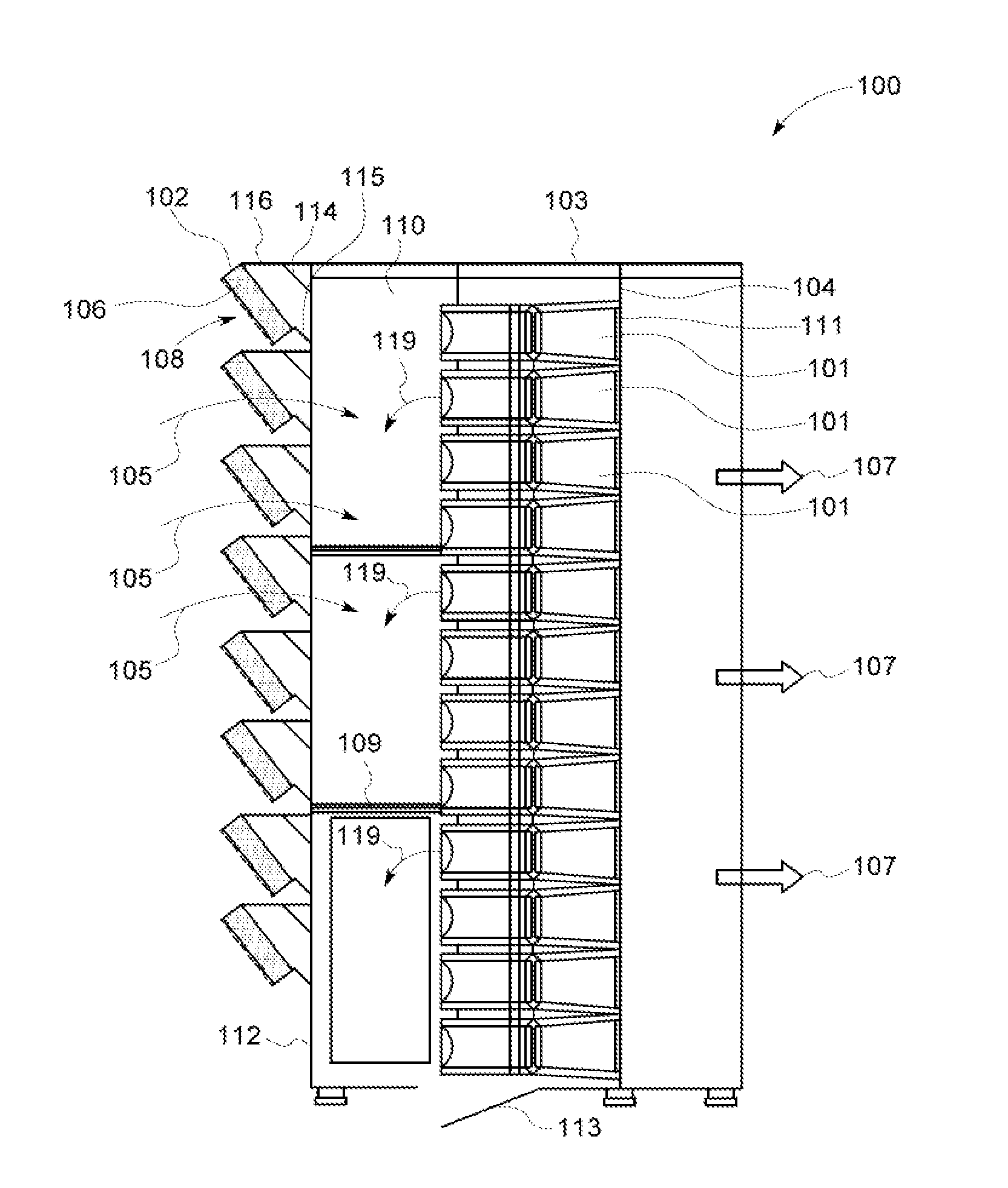
[0014]FIG. 1 is a diagram of an exemplary air treatment system 100 that includes multiple intake hoods 102, internal space 110, filters 101, coalescers 106, and a filter house 103 that receives intake airflow 105 and removes moisture and dust therefrom. Inlet air treatment system 100 then directs the filtered exit airflow 107 through downstream ducts. During operation, inlet air treatment system 100 may channel the filtered exit airflow 107 to a gas turbine, such as described above.

[0015]Ambient air pressure outside of the intake hoods 102 and dynamic pressure levels within the filter house 103, such as in the downstream air flow 107, determine a differential pressure magnitude across the intake portion of the air treatment system 100. The differential pressure may increase due to intake airflow 105 through the coalescers 106 and the filters 101, which may be caused by dust, dirt or other debris clogging air passages therein.

[0016]Inlet air treatment system 100 includes intake hoods...


PUM


Abstract

An air intake hood for channeling an incoming air flow downward in a filter house. The intake hood includes an inlet that is inclined.

Description

BACKGROUND OF THE INVENTION[0001]The subject matter disclosed herein relates to filter house air filtration, in particular, to an improved intake hood.[0002]Gas turbines include inlet air treatment systems that remove moisture and dust from air that is channeled to the compressor. Some inlet air treatment systems include moisture separators and coalescing pads that remove moisture from intake air, and final filters that remove dust and debris. During normal operating conditions, it is desired to have the inlet air treatment system channel the dehydrated and filtered air to the compressor with minimal airflow disruption and air pressure drop. Clogged air filters reduce the efficiency of the gas turbine and typically have to be pressure pulsed periodically to dislodge dust and debris which drops away from the air filters to the bottom of the filter house where a collection mechanism is employed to remove the debris.[0003]In order to efficiently clean the filters, the air flow through ...

Claims


Application Information

Patent Timeline
Patent Type & Authority Applications(United States)
IPC IPC(8): F02C7/052F02C7/04
CPCF02C7/04F02C7/052Y10T137/0536
Inventor SARASWATHI, RAJESH PRABHAKARANKIPPEL, BRADLY AARONZHANG, JIANMINMATHEW, ARUN EAPEN
Owner BHA ALTAIR
Why Eureka
Try Eureka